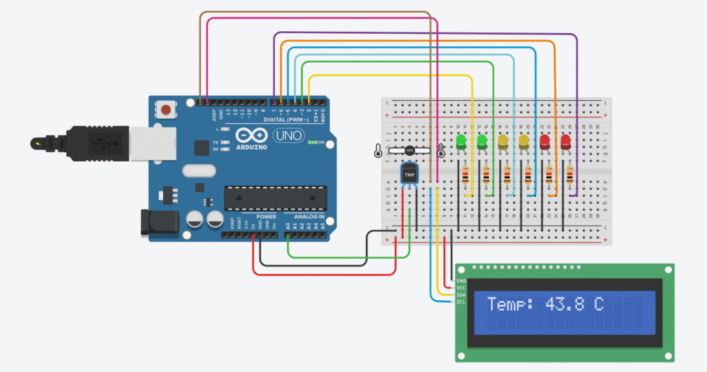
In this upgraded version of the LED temperature meter, we’ll display the current temperature in real-time on a 16×2 LCD alongside the LED bar. The LEDs light up based on temperature level, while the LCD gives you the exact number in °C.
Components Required
- Arduino Uno Starter Kit
- Bread Board
- Jumper Wires
- 5mm LEDs Assortment Pack
- Resistors ( 220 ohms recommended)
- TM36 Temperature Sensor
- 16×2 I2C LCD Display
This post may contain affiliate links. If you purchase through these links, I may earn a small commission at no extra cost to you. It helps support this blog and keeps the projects coming—thanks for your support!
TMP36 Pinout and Wiring
Facing the flat side of TMP36 with the text facing you:
| TMP36 Pin | Connects to | Description |
|---|---|---|
| 1 (VCC) | 5V | Power supply |
| 2 (VOUT) | A0 | Analog output to Arduino |
| 3 (GND) | GND | Ground |
LCD I2C Wiring
| I2C LCD Pin | Arduino Pin |
|---|---|
| GND | GND |
| VCC | 5V |
| SDA | A4 |
| SCL | A5 |
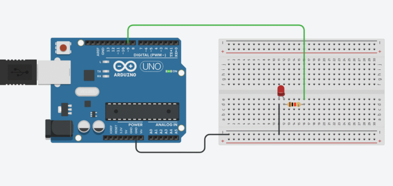
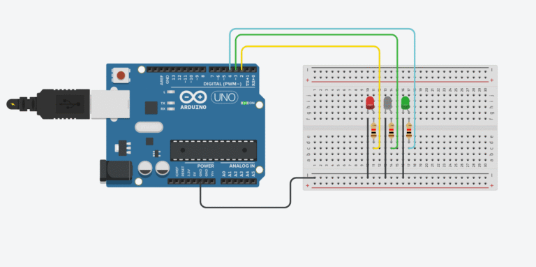
LEDs: Connect to digital pins D2 through D7, each with a 220Ω resistor.
Arduino Code
#include <Wire.h>
#include <LiquidCrystal_I2C.h>

const int tempPin = A0;
const int ledPins[] = {2, 3, 4, 5, 6, 7};
const int ledCount = 6;

LiquidCrystal_I2C lcd(0x27, 16, 2); // Adjust I2C address if needed

void setup() {
  lcd.init();             // Use lcd.init() instead of lcd.begin() for Tinkercad
  lcd.backlight();
  lcd.setCursor(0, 0);
  lcd.print("Temp: --.- C");

  for (int i = 0; i < ledCount; i++) {
    pinMode(ledPins[i], OUTPUT);
  }
}

void loop() {
  int sensorValue = analogRead(tempPin);
  float voltage = sensorValue * (5.0 / 1023.0);
  float temperatureC = (voltage - 0.5) * 100.0;

  // Display temperature on LCD
  lcd.setCursor(6, 0);
  lcd.print(temperatureC, 1);
  lcd.print(" C ");

  // Map temperature to LED level (20–40°C → 0–6 LEDs)
  int level = map(temperatureC, 20, 40, 0, ledCount);
  level = constrain(level, 0, ledCount);

  for (int i = 0; i < ledCount; i++) {
    digitalWrite(ledPins[i], i < level ? HIGH : LOW);
  }

  delay(500);
}
Visual Temperature Bar with LCD Display
This enhanced version of the temperature bar adds an I2C LCD screen to display the temperature value in real-time while lighting up LEDs as a visual indicator.
Step 1: Include libraries and define pins
#include <Wire.h>
#include <LiquidCrystal_I2C.h>

const int tempPin = A0;
const int ledPins[] = {2, 3, 4, 5, 6, 7};
const int ledCount = 6;

LiquidCrystal_I2C lcd(0x27, 16, 2); // Adjust I2C address if needed
– Wire.h and LiquidCrystal_I2C.h are needed to control the I2C LCD.
– lcd(0x27, 16, 2) initializes the LCD with I2C address 0x27 and a 16×2 layout.
Step 2: Setup LCD and LED pins
void setup() {
  lcd.init();             // Use lcd.init() instead of lcd.begin()
  lcd.backlight();
  lcd.setCursor(0, 0);
  lcd.print("Temp: --.- C");

  for (int i = 0; i < ledCount; i++) {
    pinMode(ledPins[i], OUTPUT);
  }
}
– Initializes the LCD and turns on the backlight.
– Displays a placeholder temperature on the first line.
– Configures all LED pins as OUTPUT.
Step 3: Read temperature and update display
int sensorValue = analogRead(tempPin);
float voltage = sensorValue * (5.0 / 1023.0);
float temperatureC = (voltage - 0.5) * 100.0;
– Reads the analog value and converts it into voltage.
– Applies TMP36 conversion to get temperature in Celsius.
Step 4: Display temperature on LCD
lcd.setCursor(6, 0);
lcd.print(temperatureC, 1);
lcd.print(" C ");
– Moves the cursor to overwrite the temperature section.
– Displays the temperature with 1 decimal place followed by “°C”.
Step 5: Map temperature to LEDs
int level = map(temperatureC, 20, 40, 0, ledCount);
level = constrain(level, 0, ledCount);
– Translates temperature from 20–40°C into 0–6 LED levels.
– Ensures the number of LEDs stays within the valid range.
Step 6: Light up LEDs based on temperature
for (int i = 0; i < ledCount; i++) {
  digitalWrite(ledPins[i], i < level ? HIGH : LOW);
}
– Turns on LEDs corresponding to the current temperature level.
– Creates a simple LED thermometer effect.
Step 7: Add delay to stabilize output
delay(500);
– Adds a short delay between readings to prevent flickering.
How It Works
- The TMP36 sensor outputs an analog voltage that varies linearly with temperature. At 0°C, the output is approximately 0.5V. Each 1°C change increases the output by 10mV.
- Arduino reads this voltage through pin A0 and converts it to temperature in Celsius using the formula
(voltage - 0.5) * 100.0. - The measured temperature is then displayed on the 16×2 LCD using the I2C interface, which simplifies wiring by using only 2 pins (SDA and SCL).
- At the same time, the temperature value is mapped to a number of LEDs to be lit up. For example:
- At 20°C → 0 LEDs on
- At 50°C → ~3 LEDs on
- At 100°C or above → All LEDs on
- This combination provides both a visual scale (LED bar) and a precise numeric display (LCD) for temperature monitoring.
🛠️ Optional Upgrades
- Add buzzer if temperature goes above 35°C.
- Use RGB LED instead of single-color bar.
- Add humidity sensor for combined temperature + humidity display.
- Display °F alongside °C by converting:
F = C * 1.8 + 32
🔧 Recommended Arduino Starter Kits for Beginners
If you’re just getting started with Arduino, these beginner-friendly kits will help you learn faster and avoid the headache of missing parts. They all include essential components like LEDs, resistors, jumper wires, and an Arduino-compatible board.
- Arduino Official Starter Kit
Includes a genuine Arduino UNO board, project book, and components for 15+ tutorials.
👉 Check it on Amazon - Elegoo UNO R3 Super Starter Kit
Affordable and packed with sensors, LEDs, motors, and wires — great value.
👉 View the Elegoo Kit - Freenove Ultimate Starter Kit
Includes 200+ components, an Arduino-compatible board, and 50+ example projects.
👉 See the Freenove Kit
💡 Tip: Choose a kit with a good variety of components so you can build multiple projects without buying extra parts later.