Physical Address
304 North Cardinal St.
Dorchester Center, MA 02124
Physical Address
304 North Cardinal St.
Dorchester Center, MA 02124

Want to build a DIY countdown timer with a raw 7-segment display, without any fancy modules like TM1637? Let’s do it the hardcore way — controlling each segment manually using Arduino pins. This is a great project to understand how 7-segment LEDs work under the hood.
This post may contain affiliate links. If you purchase through these links, I may earn a small commission at no extra cost to you. It helps support this blog and keeps the projects coming—thanks for your support!
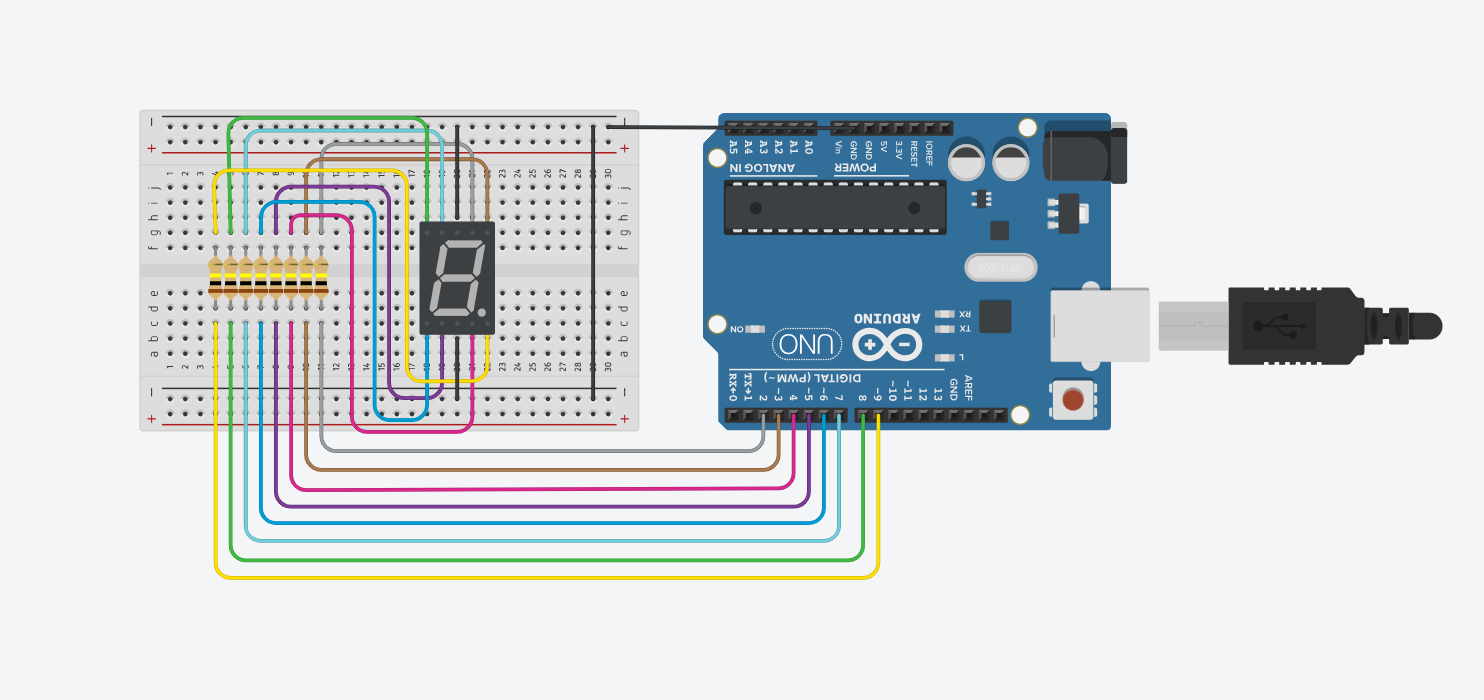
You can find the segment labels (a-g) in the datasheet of your display. In this example, we’ll assume you connect them to pins 2 through 8, and the dot to pin 9.
A 7-segment display is made up of 7 LEDs (labeled a–g) arranged in a way that they can form numbers from 0 to 9. Each segment can be turned on or off individually by sending signals from Arduino pins. Some displays also include an 8th LED as a decimal point.
There are two types of 7-segment displays:
In this project, we use a common cathode type.
Each segment in a 7-segment display is essentially an LED — and like any LED, it needs current-limiting resistors to prevent it from drawing too much current.
If you don’t add resistors:
That’s why we always place a 220Ω to 330Ω resistor in series with each segment. It keeps the current within safe limits while still making the display bright enough to read.
Assuming the following mapping from Arduino to segments:
| Arduino Pin | Segment |
|---|---|
| D2 | a |
| D3 | b |
| D4 | c |
| D5 | d |
| D6 | e |
| D7 | f |
| D8 | g |
| D9 | dot |

// Arduino seven-segment display countdown example
// Rewritten for Lee Curiosity

byte seven_seg_digits[10][7] = {
  {1, 1, 1, 1, 1, 1, 0}, // 0
  {0, 1, 1, 0, 0, 0, 0}, // 1
  {1, 1, 0, 1, 1, 0, 1}, // 2
  {1, 1, 1, 1, 0, 0, 1}, // 3
  {0, 1, 1, 0, 0, 1, 1}, // 4
  {1, 0, 1, 1, 0, 1, 1}, // 5
  {1, 0, 1, 1, 1, 1, 1}, // 6
  {1, 1, 1, 0, 0, 0, 0}, // 7
  {1, 1, 1, 1, 1, 1, 1}, // 8
  {1, 1, 1, 0, 0, 1, 1}  // 9
};

void setup() {
  for (int pin = 2; pin <= 9; pin++) {
    pinMode(pin, OUTPUT);
  }
  writeDot(0); // Turn off the dot
}

void writeDot(byte dot) {
  digitalWrite(9, dot);
}

void sevenSegWrite(byte digit) {
  byte pin = 2;
  for (byte segCount = 0; segCount < 7; ++segCount) {
    digitalWrite(pin, seven_seg_digits[digit][segCount]);
    ++pin;
  }
}

void loop() {
  for (byte count = 10; count > 0; --count) {
    delay(1000);              // Wait 1 second
    sevenSegWrite(count - 1); // Display the digit
  }
  delay(4000); // Wait 4 seconds before looping again
}
seven_seg_digits array maps each digit (0–9) to the correct ON/OFF pattern for the 7 segments.sevenSegWrite() function sends those ON/OFF values to the pins.HIGH becomes LOW and vice versa.This project gives you a hands-on feel for how 7-segment displays really work. It’s not as convenient as using a module, but it teaches you everything from pin logic to segment mapping.
If you’re just getting started with Arduino, these beginner-friendly kits will help you learn faster and avoid the headache of missing parts. They all include essential components like LEDs, resistors, jumper wires, and an Arduino-compatible board.
💡 Tip: Choose a kit with a good variety of components so you can build multiple projects without buying extra parts later.