Physical Address
304 North Cardinal St.
Dorchester Center, MA 02124
Physical Address
304 North Cardinal St.
Dorchester Center, MA 02124

Robotic arms are no longer confined to large industrial environments — they’ve made their way into classrooms, maker spaces, and home labs around the world. These robot arms have been transforming modern manufacturing for decades, helping to assemble everything from automobiles to smartphones with speed, precision, and repeatability.
For hobbyists and robotics enthusiasts, building a robotic arm is a rewarding challenge — one that teaches mechanical design, servo control, and coding, all in a single project. I previously experimented with 4 DOF wooden robotic arm, a lightweight 4-DOF arm great for learning the basics of servo coordination and inverse kinematics.
You can check the 4 DOF wooden here :
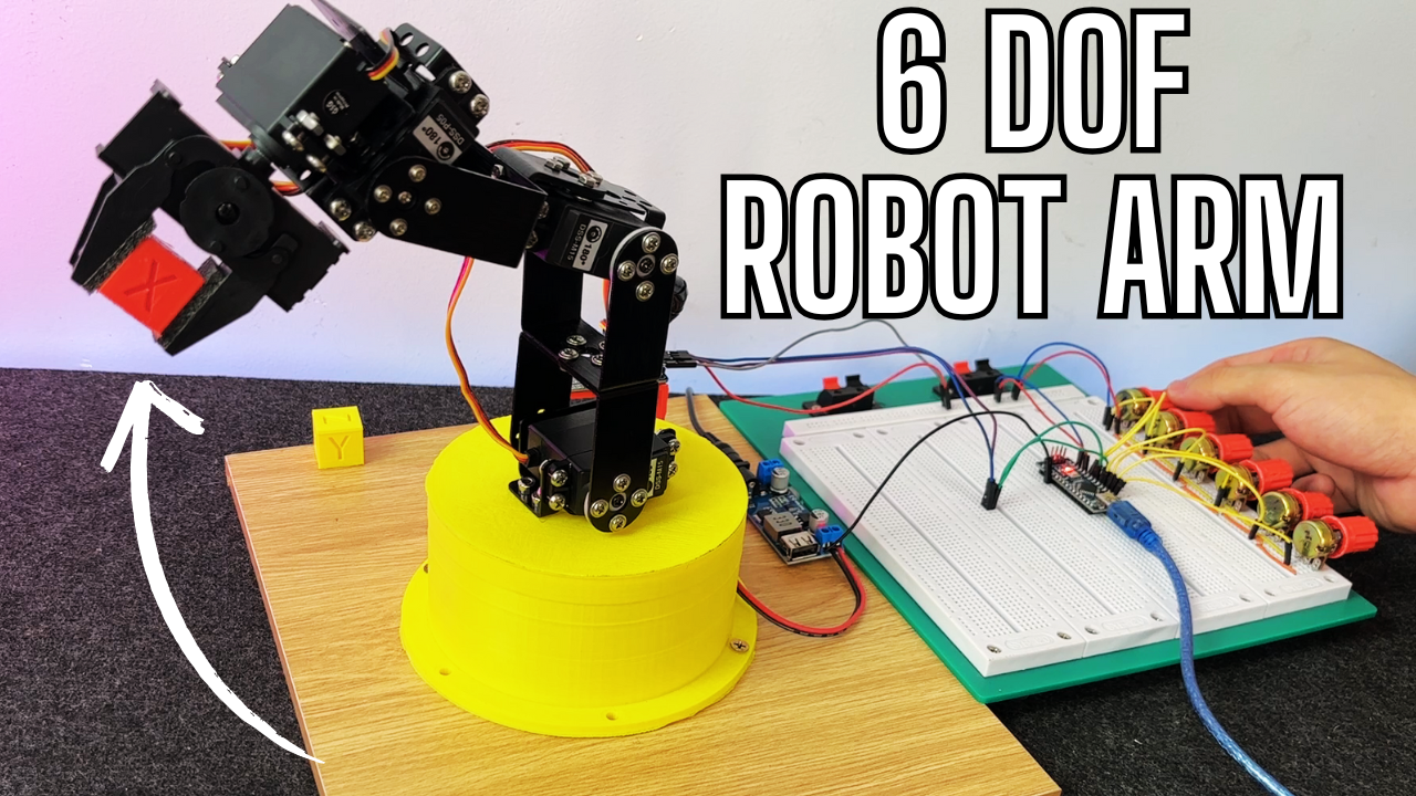
Today, we’re going a step further with a more robust and capable setup: the DFRobot 5 Degrees of Freedom Robotic Arm Kit. This kit includes all the necessary components to construct a solid aluminum robotic arm powered by high-torque servo motors and equipped with a gripper mechanism.
In this guide, I’ll walk you through:
– Assembling the robot arm step by step
– Wiring everything correctly for reliable power delivery
– Programming an Arduino Nano with potentiometers to control each axis using the PCA9685 servo driver
By the end of this tutorial, you’ll have a fully functional robotic arm that you can control manually — and a foundation to build more advanced automated motion sequences.
Let’s take a closer look at what we’ll be building.
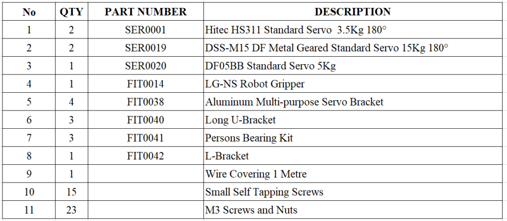
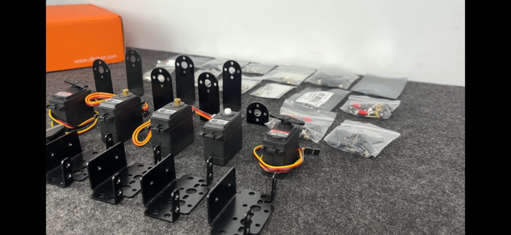
The DFRobot 5 DOF Robotic Arm Kit provides everything you need to build a compact yet powerful robotic arm — including all the essential servo motors, brackets, fasteners, and other hardware components.
All structural components are made from durable black anodized aluminum, giving the arm a sleek look and solid rigidity. This isn’t a flimsy plastic model — it’s built to handle torque and motion with precision.
The arm is driven by five standard-size servo motors, each responsible for one degree of freedom:
– 2x DSS-M15 15Kg/cm torque servos – for the base and elbow movement
– 1x DF05BB 5.5Kg/cm servo – for wrist articulation
– 2x HS311 4Kg/cm servos – to operate the gripper’s movement and jaw mechanism
All components are packaged in clearly labeled bags, which makes the unboxing and organization process much easier. The gripper itself arrives pre-assembled mechanically, so you’ll just need to install the motors before it’s ready to use.
Below is the full list of components included in the kit:
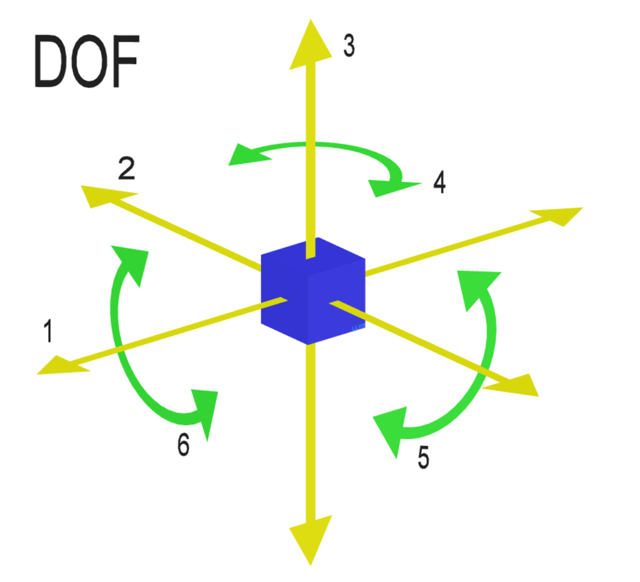
Depending on who you ask, Degrees of Freedom (DOF) can mean different things. In aerospace engineering, it typically refers to six ways an object can move in space:
– Forward & Backward
– Up & Down
– Left & Right
– Roll
– Pitch
– Yaw
But in robotics, we usually keep it simpler: DOF = number of independently controllable joints. Each servo motor in a robotic arm represents one degree of freedom.
So a 5 DOF robotic arm means it has five servo motors, and therefore five joints that can be moved individually. It’s not quite as flexible as a full industrial arm, but it’s more than enough for most hobbyist projects.
To make things easier to follow, I’ve named the sections of the robotic arm based on how they roughly compare to parts of a human arm (even though the comparison isn’t perfect — our arms are much more complex!).
Here’s the breakdown:
– Base – Think of this as the shoulder of the robot. In the stock DFRobot kit, the base is fixed — it can’t spin left or right. That means the arm can only reach things in front of it, which is kind of limiting if you’re trying to make it do anything more dynamic.
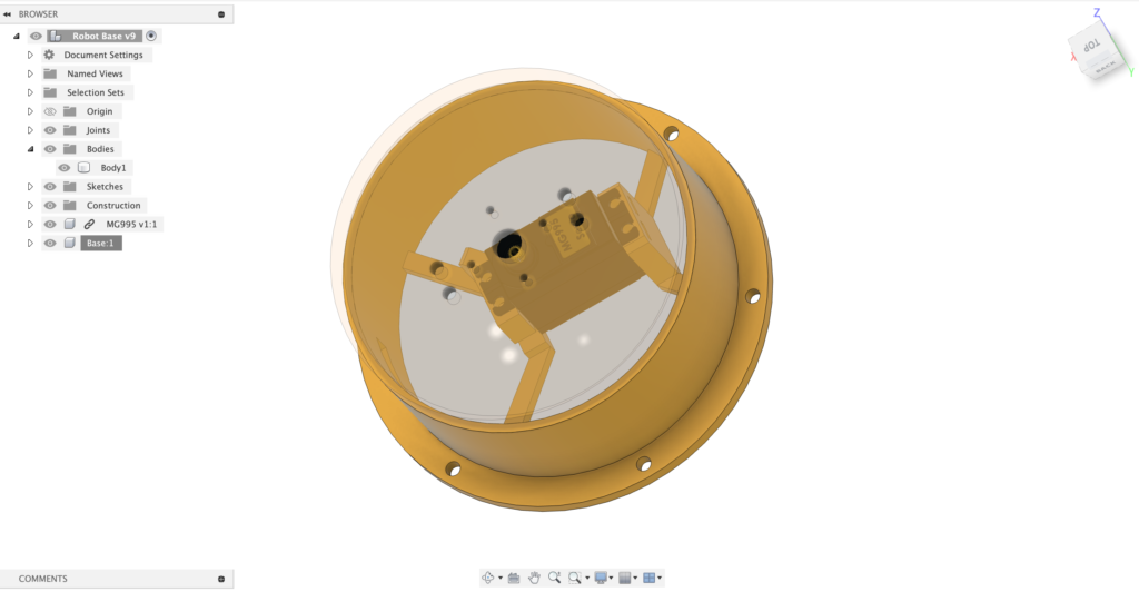
So, I designed and 3D printed a custom base that lets the entire arm rotate 360° around its vertical axis. That simple upgrade turned it into a proper 6 DOF arm, and honestly, it made a huge difference in how useful the arm feels during testing.
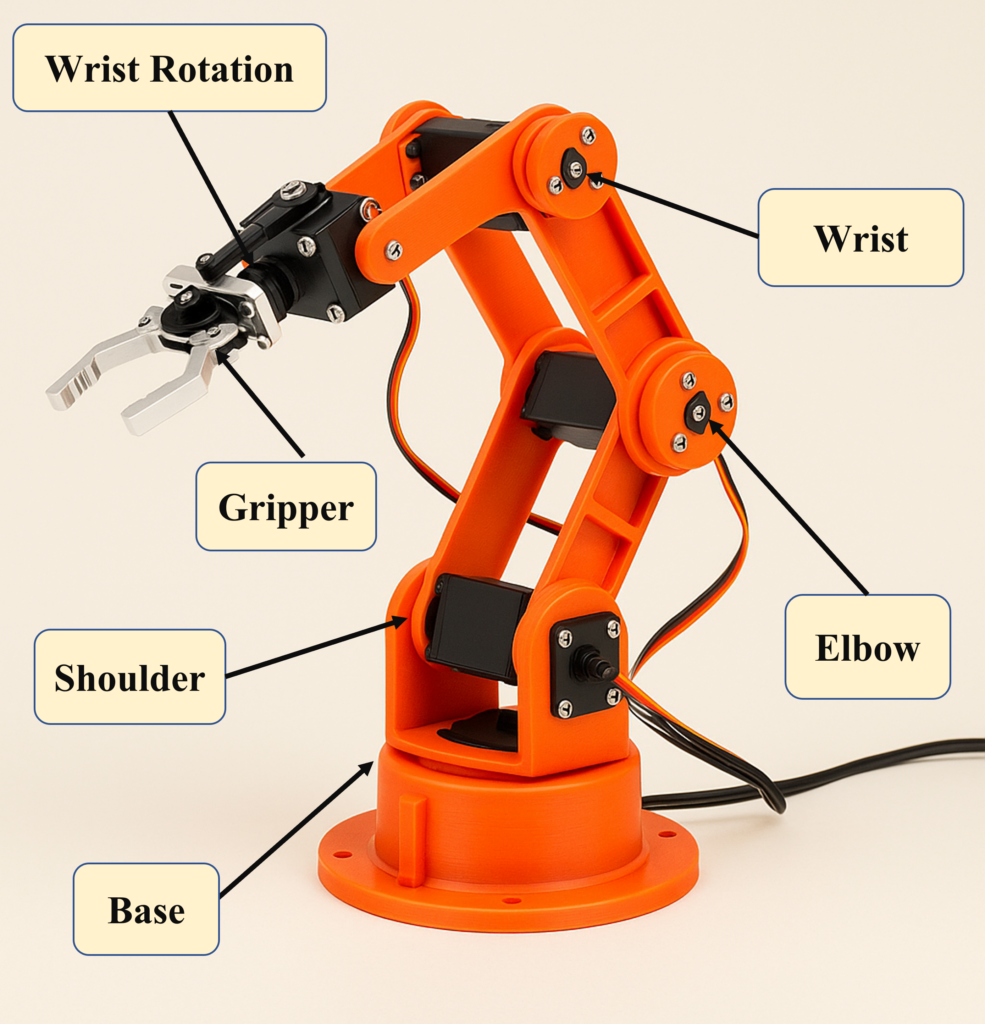
– Elbow – The first joint that allows the arm to bend, just like your elbow.
– Wrist – Helps adjust the angle of the gripper. It doesn’t rotate like your wrist might, but it adds a critical range of movement.
– Wrist Rotation – This lets the gripper spin left or right (about 90° each way). Think of it as a simple wrist twist.
– Jaws – The gripper itself, which opens and closes like a pair of pliers. You can use it to pick up small objects like plastic parts, screws, or even LEGO bricks.
So technically, the original kit gives you 5 Degrees of Freedom, but with the rotating base I added, it’s now a 6 DOF arm — which opens up way more possibilities, especially for things like pick-and-place demos or automated tasks.
The DFRobot 5 DOF Robotic Arm Kit follows a structure that’s pretty standard across many hobby-grade robotic arms — so if you’ve worked with similar kits before, you’ll feel right at home. Even if you haven’t, don’t worry — the build process is straightforward and very easy to follow.
Also, if you’re the type who loves to customize, you can totally build a similar arm by sourcing parts individually from the DFRobot; they sell almost every component separately, which is super helpful if you want to build a custom variant.
Now, let’s go through the full assembly sequence I followed when putting the arm together. Trust me — laying out the steps like this helps avoid a lot of backtracking.
1. Assemble the Gripper
2. Assemble the Double U-Bracket
3. Assemble the Elbow Motor Mount with Brackets
4. Assemble the U-Bracket with the Elbow
5. Install the Wrist Motor with Brackets
6. Assemble the Wrist Motor Mount with Gripper Mount
7. Assemble the Whole robot arm to the 3D Printing Base
If you have any questions about this project, don’t hesitate to drop a comment on this video — I’ll do my best to explain everything clearly!
Check out the video for the full assembly process:
Arduino Controller
One of the best decisions I made in this build was to use a PCA9685 16-channel PWM controller. I mounted it directly onto the robot arm to keep wiring neat and make controlling the servos much easier.
If you haven’t heard of it, the PCA9685 is a breakout board developed by Adafruit that uses the I2C communication protocol to control up to 16 PWM outputs — which is perfect for servo motors. That means with just two wires (SDA & SCL), you can control all your servos without burning through your Arduino’s PWM pins.
Each servo gets its own channel, and the PCA9685 takes care of all the timing in the background. That way, your Arduino doesn’t get bogged down trying to generate accurate PWM signals for every motor. In short: less CPU load, cleaner code, and way more expandability.
Here’s why it’s perfect for this project:
– I needed to control Six servo motors (plus one more if you do the rotating base mod)
– I only had a limited number of PWM-capable pins on my Arduino Nano
– The PCA9685 provides high-resolution (12-bit) PWM, which means smoother and more precise servo motion
– It’s powered independently, so I could give the servos proper 5–6V power without stressing the Arduino
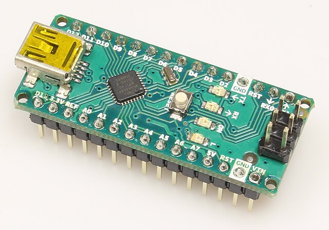
Arduino Nano
Normally, I’d use an Arduino Uno for projects like this — it’s cheap, reliable, and has just enough I/O for most builds. But this time, I ran into a limitation that made me switch to the Nano Board.
See, I wanted to build a manual controller for my robot arm using six potentiometers, one for each servo. This setup would give me full control over all 6 degrees of freedom, including the rotating base I added with a 3D printed turntable.
Now, the Uno does have six analog inputs, so on paper, it sounds like a perfect fit. But here’s the thing:
Pins A4 and A5 on the Uno are used for I2C communication — and that’s exactly what I need to talk to the PCA9685 servo driver.
Even if your board has separate SDA/SCL pins, they’re still internally connected to A4 and A5. Which means… they’re not usable for reading pots.
So really, you only get four usable analog inputs — and I needed six.
That’s when I switched to the Arduino Nano, and it solved everything.
The Nano gives you eight analog inputs (A0–A7). Even after using A4 and A5 for I2C, I still had six fully available analog pins, which was exactly what I needed. No pin juggling, no headaches and no messy wires.
It’s also super compact, which makes it easy to mount — especially if you’re working on a small robot base or need to keep things tidy. I used a breadboard to plug in the Arduino Nano, and honestly, that made testing and rewiring way easier.
Being able to pull out a pin or swap connections without soldering is a big win when you’re still experimenting.
Just a quick tip: remember to select “Arduino Nano” as the board type in the Arduino IDE before uploading your code — yeah… I forgot once and sat there wondering why nothing worked.
Honestly, wiring this thing up wasn’t too bad — thanks to the PCA9685, I didn’t have to stress about PWM pins or timing issues. Just two wires from the Arduino (I2C), and it handles all the servos like a champ.
I mounted the PCA9685 right on the robot arm, and I highly recommend doing that if you’re building something similar. It keeps the wiring short and tidy — no need to run long servo wires across your desk or back to a breadboard. Plus, I’m planning to throw in a couple more I2C sensors later on, so having everything in one spot just makes sense.
Of course, if you prefer doing it the traditional way, you can totally slap the PCA9685 next to your Arduino Nano on a breadboard. No judgment — whatever works best for your setup.
So, here’s how I did the control part.
I’m using six potentiometers, one for each joint on my 6 DOF arm (yep, including the rotating base I added). Twist a knob, the arm moves. It’s dead simple — and yeah, kinda addictive once you start playing with it.
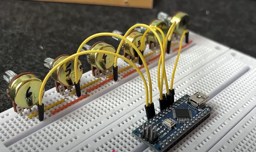
Wiring the pots is pretty basic:
– One side goes to GND
– The other side to 5V (from the Nano)
– The middle pin (wiper) connects to an analog input on the Nano
And here’s how I assigned them:
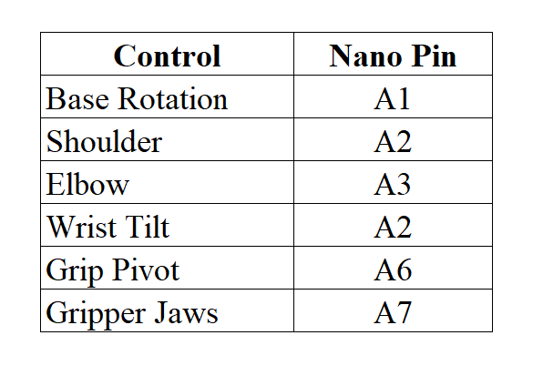
Quick heads-up:
Pins A4 and A5 are used for I2C — so they’re off-limits if you’re using the PCA9685 (which you should be). That’s why having those extra pins on the Nano really saved me.
Alright, so once you’ve got everything wired up on the Arduino side, it’s time to hook up the PCA9685 — this little board is basically your servo controller.
There are two I2C headers on the PCA9685, and honestly, either one works. I used the one that was physically closer to the front of my robot arm to keep the wiring cleaner — but you do you. They’re electrically the same.
Now plug in your servo motors to the output channels. I’m using all 6 channels (because 6 DOF, baby ), but you can leave some empty if you’re not there yet.
Quick heads-up:
Make sure your servo plugs go in the right way. The brown or black wire (GND) goes on the outside edge of the board (next to the label). Plug it in backward, and you might get nothing — or worse, your servo starts twitching like it’s possessed.
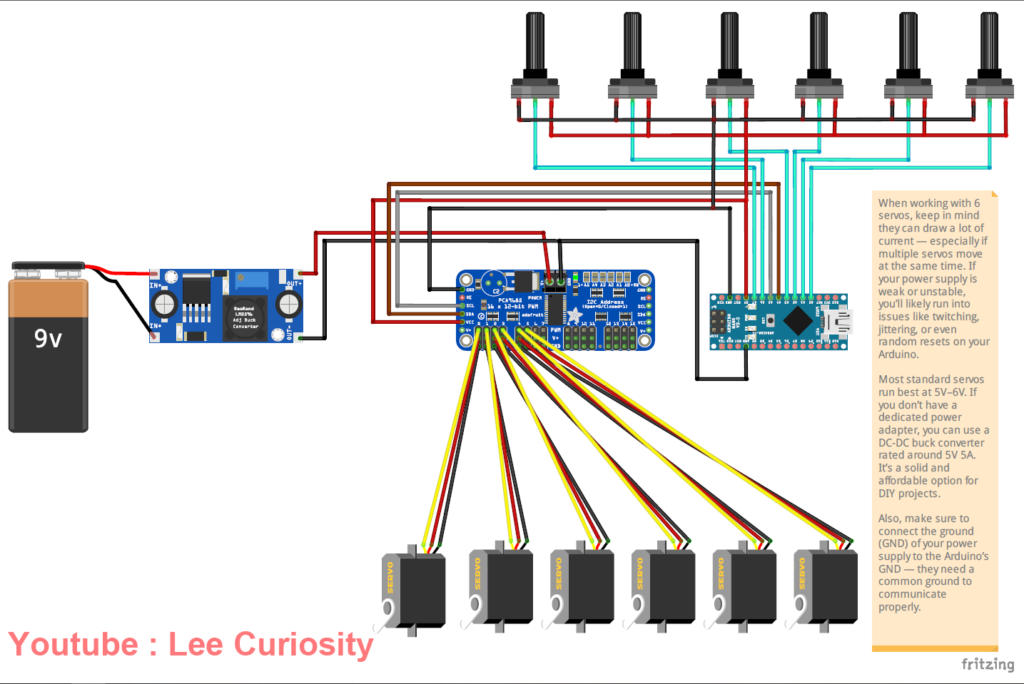
Here’s something important: servos are power-hungry creatures. Especially those chunky high-torque ones like the DSS-M15. You absolutely should not try to power them directly from the Arduino — unless you enjoy brownouts and random resets.
I’m using a 5V 5A buck converter, which is enough for light-duty movement and testing.
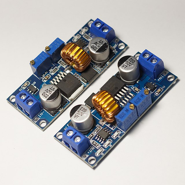
But — if you’re planning to build anything more advanced, like a “save and play” routine where multiple joints move at once, you’ll need a stronger power supply.
These servos, especially the high-torque ones, draw way more current than you’d expect when they all move together.
My honest recommendation?
Get a dedicated 5V 10A power supply just for the servos.
Or use a variable bench power supply that lets you tweak voltage and monitor current draw. Either way, the key is making sure it can handle the peak load without dropping voltage.
Connect your power supply to the V+ and GND screw terminals on the PCA9685. And don’t forget:
You must connect the ground (GND) of your power supply to the Arduino’s ground too. If you don’t share a common ground, things get weird. Trust me.
//  Lee Curiosity
// Innstall the Adafruit_PWMServoDriver for PCA9685 for control the servo motors
#include <Wire.h>
#include <Adafruit_PWMServoDriver.h>

Adafruit_PWMServoDriver pwm = Adafruit_PWMServoDriver();

// Analog pins & PWM channels for servos
const int sensorPins[6] = {A0, A1, A2, A3, A6, A7};
const int pwmChannels[6] = {0, 1, 2, 3, 4, 5};

// Standard servo pulse range
const int minPulse = 500;
const int maxPulse = 2500;
const int minPWM = 150;
const int maxPWM = 600;

// 360° base servo — stop around 375
const int baseMin = 300;
const int baseMax = 450;

// Button config
const int buttonPin = 6;
bool isPlaying = false;

int steps[20][6];  // Store up to 20 steps
int stepCount = 0;

unsigned long buttonPressTime = 0;
bool buttonPressed = false;

// Store previous analog values to avoid jitter
int lastAnalogVals[6] = {0};

void setup() {
  Serial.begin(115200);
  pwm.begin();
  pwm.setPWMFreq(50);

  pinMode(buttonPin, INPUT_PULLUP);
  Serial.println("🤖 Ready to SAVE & LOOP PLAYBACK");
}

void loop() {
  if (!isPlaying) {
    // Manual control mode
    for (int i = 0; i < 6; i++) {
      int val = analogRead(sensorPins[i]);
      if (abs(val - lastAnalogVals[i]) > 5) {  // Update only if value changes significantly
        lastAnalogVals[i] = val;
        int pwmVal;

        if (i == 0) {
          pwmVal = map(val, 0, 1023, baseMin, baseMax);
        } else {
          int pulse = map(val, 0, 1023, minPulse, maxPulse);
          pwmVal = map(pulse, minPulse, maxPulse, minPWM, maxPWM);
        }

        pwm.setPWM(pwmChannels[i], 0, pwmVal);
      }
    }

    // Button handling
    if (digitalRead(buttonPin) == LOW) {
      if (!buttonPressed) {
        buttonPressed = true;
        buttonPressTime = millis();
      } else {
        if (millis() - buttonPressTime > 2000) {
          Serial.println("▶️ STARTING LOOP PLAYBACK...");
          isPlaying = true;
          buttonPressed = false;
          delay(500);
        }
      }
    } else {
      if (buttonPressed && millis() - buttonPressTime < 500) {
        if (stepCount < 20) {
          for (int i = 0; i < 6; i++) {
            steps[stepCount][i] = analogRead(sensorPins[i]);
          }
          Serial.print("✅ Saved step "); Serial.println(stepCount);
          stepCount++;
          delay(300);
        } else {
          Serial.println("⚠️ Memory full (20 steps max)");
        }
      }
      buttonPressed = false;
    }

    delay(30);
  } else {
    // === LOOP PLAYBACK: Pick - Drop - Return to base ===
    while (true) {
      for (int s = 1; s < stepCount; s++) {
        moveToStep(s);
        delay(1000);
      }
      moveToStep(0);
      delay(1000);
    }
  }
}

void moveToStep(int s) {
  for (int i = 0; i < 6; i++) {
    int val = steps[s][i];
    int pwmVal;

    if (i == 0) {
      pwmVal = map(val, 0, 1023, baseMin, baseMax);
    } else {
      int pulse = map(val, 0, 1023, minPulse, maxPulse);
      pwmVal = map(pulse, minPulse, maxPulse, minPWM, maxPWM);
    }

    pwm.setPWM(pwmChannels[i], 0, pwmVal);
  }
}