In this tutorial, we’ll build a simple but powerful Arduino LED Dimmer using a potentiometer and PWM (Pulse Width Modulation). You’ll get to understand how PWM works, and how you can control the brightness of an LED based on the position of a potentiometer.
We’ll also simulate how it works, walk through the code line by line, and test it directly on your Arduino board.
No more waiting — let’s dive in!
LED Dimming with Arduino
To build this project, you’ll need the following components:
- Arduino Uno Starter Kit
- Bread Board
- Jumper Wires
- 5mm LEDs Assortment Pack
- Resistors ( 220 ohms recommended)
- 10k Potentiometers
- This post may contain affiliate links. If you purchase through these links, I may earn a small commission at no extra cost to you. It helps support this blog and keeps the projects coming—thanks for your support!
This dimmer project works by combining two things:
- An analog input (from the potentiometer)
- And a PWM output (to control the LED)
As you rotate the potentiometer, it changes the analog value that Arduino reads. Then, using the analogWrite() function, the Arduino outputs a PWM signal with a duty cycle that matches the potentiometer’s position — making the LED dim or brighten smoothly.
On most Arduino boards, PWM pins are marked with a tilde symbol (~). These pins can generate PWM signals via analogWrite().
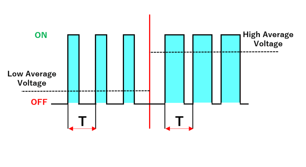
Wait… What is PWM?
Pulse Width Modulation (PWM) is a technique used to simulate analog output using digital signals.
It rapidly switches the pin between HIGH and LOW states. By adjusting the duration of the HIGH signal within each cycle (called the duty cycle), we can “fake” different voltage levels.
A duty cycle of 0% = always OFF (0V average)
A duty cycle of 50% = ON half the time → ~2.5V average
A duty cycle of 100% = always ON (5V average)
Many components like LEDs, motors, or fans don’t react to rapid switching — instead, they respond to the average voltage, which is what makes PWM so effective.
PWM example:
Let’s say you have an old-school fan with no speed settings.
Now imagine you sit there and manually flip the ON/OFF switch like this:
ON for 1 second, OFF for 1 second → fan spins slowly
ON for 3 seconds, OFF for 1 second → fan spins faster
ON all the time → full speed
That’s basically how PWM works. You’re not changing the actual voltage — you’re just faking different power levels by adjusting how long the signal stays ON.
Steps to Build the Circuit (With Full Explanation)
1. Start with the Ground (GND)
In electronics, ground is everything.
It acts like the “reference level” for all voltages in your system. Without a common ground, your circuit may behave weirdly — or not work at all.
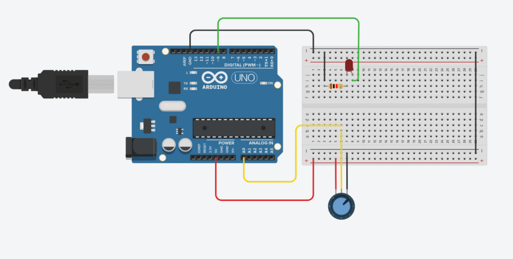
So, the first thing we’ll do is connect the Arduino’s GND pin to the breadboard’s negative (–) rail using a black jumper wire (black is standard for ground wires).
⚠️ Tip: Always use one GND rail for all your components. This way, they all “speak the same electrical language”.
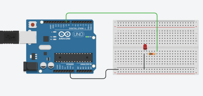
2. Connect the LED (Output Device)
Step-by-step:
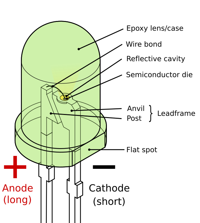
Take your LED and identify its legs:
The shorter leg = cathode (–)
The longer leg = anode (+)
Connect the cathode to the GND rail of the breadboard (directly or via a short black wire)
Plug the anode into a free row (not touching anything else yet)
Insert a 220Ω resistor in series with the anode leg.
One side goes into the same row as the anode, the other into another new row.
Now use a jumper wire to connect the other side of the resistor to an Arduino PWM-compatible pin, like pin 9.
These pins support analogWrite() — they have a tilde (~) symbol on most Arduino boards.
📌 Why resistor? Without it, your LED might draw too much current and burn out.
💡Why PWM pin? Because we’ll dim the LED by sending PWM signals from this pin.
3. Add the Potentiometer (Input Device)
The potentiometer has 3 legs, and acts like a voltage divider.
As you turn the knob, the middle leg (called the wiper) outputs a variable voltage between 0V and 5V.
Wiring:
Connect one outer leg to the GND rail
Connect the other outer leg to the 5V pin on the Arduino
Plug the middle leg into analog pin A0
Now when you turn the knob, A0 will read values from 0 (fully left) to 1023 (fully right).
We’ll use this value to control the LED’s brightness via PWM.
Arduino Code – LED Dimmer
In this project, we’ll use a potentiometer to control the brightness of an LED. The potentiometer is read using analogRead(), which gives us a value between 0 and 1023. We then scale that to a value between 0 and 255 using map(), and pass it into analogWrite() to control the LED.
// Arduino LED Dimmer using Potentiometer and PWM

const int potPin = A0;     // Potentiometer connected to analog pin A0
const int ledPin = 9;      // LED connected to digital PWM pin 9

int potValue = 0;          // Raw value from potentiometer (0–1023)
int brightness = 0;        // PWM value (0–255)

void setup() {
  pinMode(ledPin, OUTPUT);
}

void loop() {
  // 1. Read the potentiometer
  potValue = analogRead(potPin);   // Reads value between 0–1023

  // 2. Map it to PWM range
  brightness = map(potValue, 0, 1023, 0, 255);  // Scale to 0–255

  // 3. Write PWM value to LED
  analogWrite(ledPin, brightness);  // Dims LED based on potentiometer

  delay(10); // Small delay to smooth out reading
}
Breaking Down the Code
Let’s walk through the code step-by-step to understand what’s happening behind the scenes.
Step 1: Define the pins
const int potPin = A0;     // Potentiometer connected to analog pin A0
const int ledPin = 9;      // LED connected to digital PWM pin 9
We start by defining two pins:
– potPin is the analog input pin where the potentiometer is connected (A0).
– ledPin is the PWM-enabled digital pin where the LED is connected (pin 9 in this case).
Step 2: Set up variables
int potValue = 0;          // Raw value from potentiometer (0–1023)
int brightness = 0;        // PWM value (0–255)
We create two variables:
– potValue stores the raw analog input from the potentiometer.
– brightness will store the PWM signal we send to the LED.
Step 3: Setup function
void setup() {
  pinMode(ledPin, OUTPUT);
}
This function runs once when the Arduino is powered on. It sets ledPin as an output so we can control it using PWM.
Step 4: Loop – Read, Map, and Write
void loop() {
  potValue = analogRead(potPin);
  brightness = map(potValue, 0, 1023, 0, 255);
  analogWrite(ledPin, brightness);
  delay(10);
}
This loop keeps running repeatedly. Here’s what happens step-by-step:
- Read:
analogRead(potPin)reads the potentiometer’s position (0–1023). - Map:
map(...)converts it to a PWM-friendly range (0–255). - Write:
analogWrite(...)sends a PWM signal to control LED brightness. - Delay:
delay(10)smooths out rapid fluctuations.
💡 How it works:
As you turn the potentiometer knob, the LED fades in or out. You’re turning analog movement into a digital signal, and the Arduino is translating that into visible brightness using PWM. Pretty cool, right?
🔧 Recommended Arduino Starter Kits for Beginners
If you’re just getting started with Arduino, these beginner-friendly kits will help you learn faster and avoid the headache of missing parts. They all include essential components like LEDs, resistors, jumper wires, and an Arduino-compatible board.
- Arduino Official Starter Kit
Includes a genuine Arduino UNO board, project book, and components for 15+ tutorials.
👉 Check it on Amazon - Elegoo UNO R3 Super Starter Kit
Affordable and packed with sensors, LEDs, motors, and wires — great value.
👉 View the Elegoo Kit - Freenove Ultimate Starter Kit
Includes 200+ components, an Arduino-compatible board, and 50+ example projects.
👉 See the Freenove Kit
💡 Tip: Choose a kit with a good variety of components so you can build multiple projects without buying extra parts later.