Physical Address
304 North Cardinal St.
Dorchester Center, MA 02124
Physical Address
304 North Cardinal St.
Dorchester Center, MA 02124


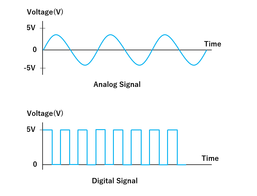
Digital signals are binary — they can only be either 0 or 1. Analog signals, however, have a continuous range of values and are not limited to just two states. Both types of signals are found in electronic systems, but they’re processed in very different ways.
When we need to read an analog input, we typically use a sensor to gather real-time analog data. That signal is then passed through an Analog-to-Digital Converter (ADC) so a microcontroller can interpret it in digital form. But what about the reverse? What if we want our microcontroller to influence or control an analog output device like a speaker, motor, or LED dimmer?
Some microcontrollers are equipped with a Digital-to-Analog Converter (DAC) that lets them produce a true analog signal for these purposes. External DAC modules are also available. However, DACs are relatively expensive and require more silicon space in hardware design, making them less ideal for compact and cost-effective systems.
To address these limitations and simulate the effect of analog output, we often use a technique called Pulse Width Modulation (PWM). It’s a clever and affordable workaround that provides analog-like behavior using digital signals.
PWM, or Pulse Width Modulation, is a method of controlling analog components through a digital signal. Essentially, it allows digital devices like microcontrollers to emulate analog output by turning a pin ON and OFF at a rapid pace, varying how long it stays in the “on” state. This switching frequency and duty cycle can be adjusted to create an average signal level that behaves similarly to a true analog output.
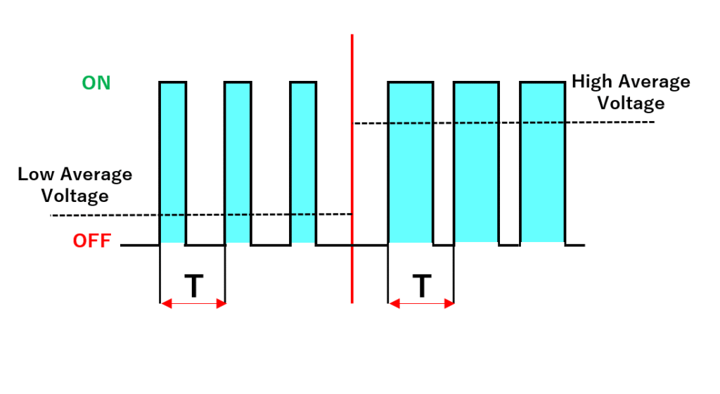
With electrical devices, you can control the average power or current they receive by adjusting how long the power supply is on versus off during each cycle. By keeping the “ON” time longer than the “OFF” time, you raise the average voltage or current; reversing that lowers the output. Even though the signal is just toggling between two states (ON/OFF), the device behaves as if it’s receiving a variable (analog) signal. This is the essence of how PWM works.
Let’s use a practical analogy to understand this better. Imagine you have a ceiling fan at home with only a simple switch — no speed control knob. It either runs at full speed when turned on or stops completely when turned off. Now, let’s say you want to operate the fan at 50% of its maximum speed. Sounds tricky, right?
But it’s actually possible. While we don’t advise doing this in real life, you could manually flip the switch on until the fan reaches half speed, then turn it off. As it starts to slow down, you turn it on again. By repeating this on-off pattern quickly, you can maintain the fan at roughly half speed. This technique relies on the fan’s natural inertia to smooth out the bursts of power, which is exactly how PWM functions — rapid on-off switching to simulate variable output.
It’s important to note that frequently switching devices like this in reality (especially something like a ceiling fan) is not recommended due to electrical and mechanical stress. But it perfectly illustrates how PWM manipulates timing to control power.
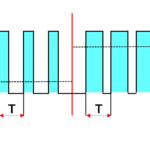
In a PWM signal, the “ON” phase is the pulse, and how long the signal remains high is called the pulse width. The total time it takes to complete one cycle is the period (T). Modulation refers to adjusting this pulse width to create the effect we want. So, when we talk about Pulse-Width Modulation, we’re referring to the process of varying how long the signal stays ON during each cycle to control the average output.
In PWM, we define “ON-TIME” using a term called the duty cycle. It expresses how much of one full cycle the signal remains in its high (on) state, represented as a percentage.
For instance, suppose you have a 10V signal and a total cycle time of one second:
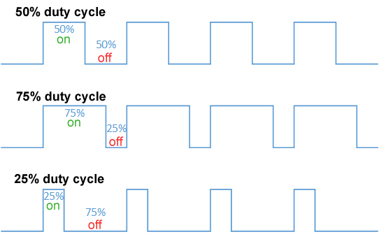
If the signal is ON for 0.5 seconds and OFF for 0.5 seconds, the duty cycle is 50%, and the average voltage output is 5V.
If it stays ON for 0.75 seconds and OFF for only 0.25 seconds, the duty cycle becomes 75%, resulting in an average of 7.5V.
You can visualize this with waveforms showing various duty cycles and their corresponding average outputs.
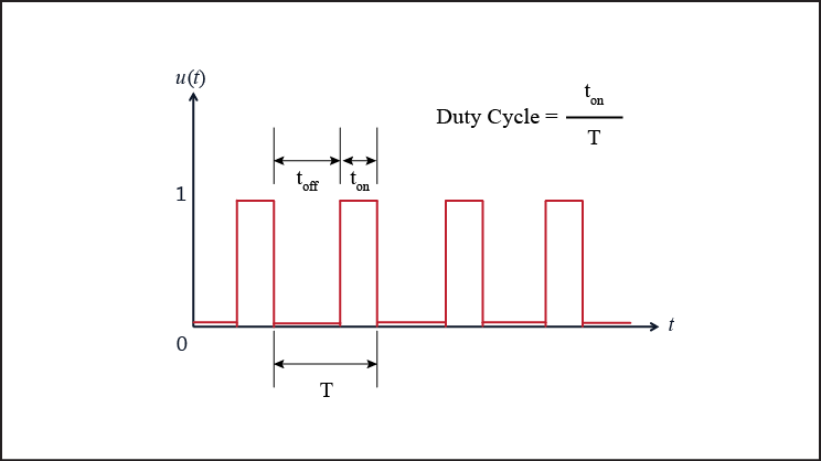
Here’s the basic formula for calculating duty cycle:
Duty Cycle (%) = (Ton / (Ton + Toff)) × 100Where:
Once you’ve calculated the duty cycle, you can find the average output voltage using:
Vavg = (Duty Cycle / 100) × VmaxWhere:
Besides duty cycle, another key parameter of a PWM signal is its Frequency — the number of complete ON-OFF cycles per second. It’s measured in hertz (Hz).
The right frequency depends heavily on your application. For example, to create a smooth dimming effect for an LED, the PWM signal should operate at a high enough frequency so the rapid flickering isn’t visible to the human eye. A PWM signal at 1Hz with a 20% duty cycle will cause a visible blink, but at 100Hz or higher, the LED appears to dim smoothly.
Lower frequencies might be used when controlling motors or heating elements, where flicker isn’t a concern and slower modulation is acceptable.
PWM signals can be generated in several ways:
Microcontroller boards like the Arduino Uno make it extremely simple to produce PWM. You can just use the analogWrite(pin, value) function. The value can range from 0 to 255:
It’s worth noting that not all pins on the Arduino Uno can generate PWM signals. Only pins 3, 5, 6, 9, 10, and 11 support this function — they’re marked with a tilde ~ on the board.
Internally, PWM is handled using timers and registers. In higher-end microcontrollers like STM32, ESP32, or Raspberry Pi Pico, the PWM generation is more customizable, allowing adjustments to resolution and frequency with greater precision.
PWM is a widely used technique thanks to its simplicity, efficiency, and versatility. Here are some common real-world uses:
Thanks to its ability to provide precise control with minimal power loss, PWM is a go-to method for controlling analog behavior in a world of digital devices.
No, PWM is not a true analog signal. It’s a digital signal that simulates analog behavior by rapidly switching between ON and OFF states. The resulting average voltage can mimic analog output, especially when passed through a low-pass filter (like an RC circuit). But it’s still fundamentally digital.
Use PWM for tasks like LED dimming or motor control. Use DAC when you need smooth analog signals — like for audio or high-precision sensors.
This usually happens when the PWM frequency is too low (below ~60Hz). Our eyes can detect the rapid ON/OFF flicker. To fix this, increase the PWM frequency. On Arduino Uno, the default PWM frequency is ~490Hz (which is fine for LEDs). If you’re using custom timers or other boards, set it to 100Hz or higher for smooth lighting.
analogWrite() accept on Arduino?The analogWrite() function accepts values from 0 to 255, representing the duty cycle:
analogWrite(pin, 0) → 0% duty cycle (always OFF)analogWrite(pin, 127) → ~50% duty cycleanalogWrite(pin, 255) → 100% duty cycle (always ON)Internally, Arduino uses an 8-bit resolution for PWM, hence the 0–255 range.
[…] If you’re curious how that works, check out this guide: PWM (Pulse Width Modulation) Explained – How Digital Pins Simulate Analog Output […]
[…] Pulse Width Modulation (PWM) is a technique used to simulate analog output using digital signals. […]