Physical Address
304 North Cardinal St.
Dorchester Center, MA 02124
Physical Address
304 North Cardinal St.
Dorchester Center, MA 02124


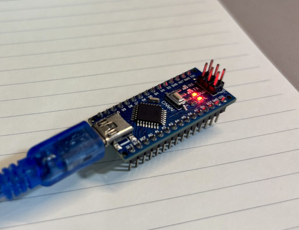
Whether you’re building your first project or just need a refresher, this guide walks through all the key pins and onboard components of the Arduino Nano. We’ll cover power inputs, I/O, communication protocols, and what each part of the board actually does.

Vin: This is where you connect an external power supply to the board. The input range is typically 6V to 12V DC. This voltage goes directly into the onboard 5V voltage regulator. Note: there’s no reverse polarity protection, so be sure to connect positive to Vin and negative to GND.
3.3V Pin: This outputs a regulated +3.3V supplied by the FT232RL chip. It can deliver a maximum current of around 50mA.
5V Pin: This pin provides a regulated +5.0V, sourced from the LM1117IMPX-5.0 voltage regulator. The amount of current available depends on the power source minus the current consumed by onboard components (usually <50mA):
When powered via USB, the available current is limited to 100mA if using a passive USB hub and 500mA with a standard USB port.
When powered through Vin, the regulator’s 800mA max rating applies. However, due to heat dissipation and higher input voltages, expect usable current to be around 400–500mA.
GND: These are the ground pins, which act as the reference voltage (0V) for the entire board.
AREF: This is the analog reference pin used to provide a custom voltage reference for the ADC.
RESET: This pin allows an external reset signal to be applied to the board, similar to pressing the reset button.
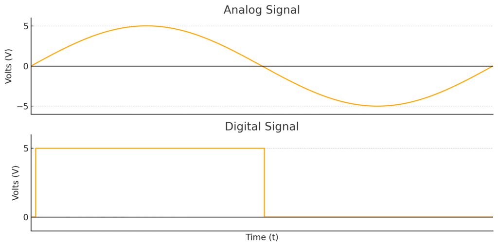
The Arduino Nano includes 8 analog input pins: A0 to A7. These are connected to a 10-bit Analog-to-Digital Converter (ADC) inside the ATmega328P, which converts analog signals (0–5V) into a digital value ranging from 0 to 1023.
Each reading provides a resolution of approximately 4.9mV. The analogRead() function takes about 100 microseconds per read, allowing for a theoretical maximum of roughly 10,000 samples per second.
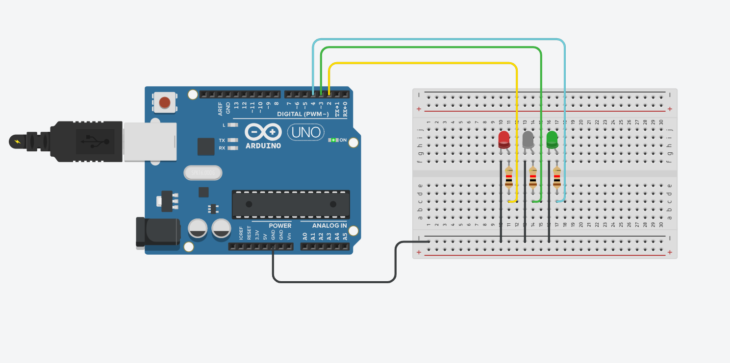
The Arduino Nano offers 20 total digital I/O pins labeled D0 to D19. These pins can be used as inputs or outputs using the standard Arduino functions: pinMode(), digitalRead(), and digitalWrite().
Each digital pin operates at 5V logic and can safely source or sink up to 40mA of current. Additionally, internal pull-up resistors ranging from 20KΩ to 50KΩ can be activated through software when a pin is configured as an input.
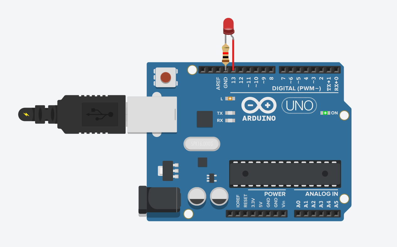
Pin D13 is connected to the onboard LED through a resistor. This configuration affects its behavior when used as a digital input. If the internal pull-up resistor is enabled, the voltage level at this pin can hang around 1.7V instead of the expected 5V, causing it to read LOW. If using D13 as a digital input, it’s recommended to configure the pin as INPUT and connect an external pull-down resistor for reliable operation.
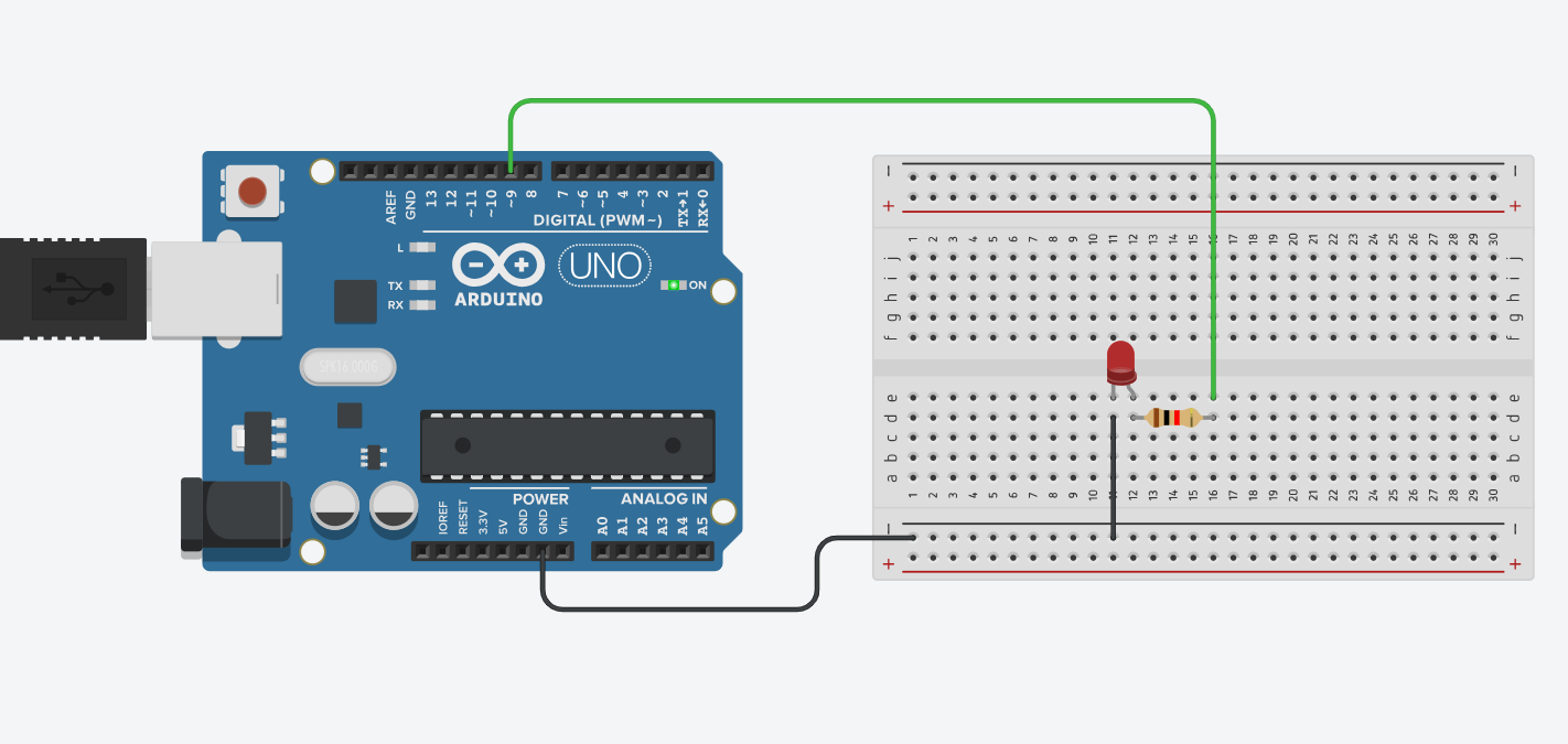
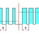
Six of the digital I/O pins — D3, D5, D6, D9, D10, and D11 — support Pulse-Width Modulation (PWM). These pins are typically marked with a ~ symbol in diagrams. PWM allows you to generate pulses with specific duty cycles, which are commonly used for dimming LEDs, controlling motor speed, and creating analog-like signals.
You can use the analogWrite(pin, value) function in the Arduino IDE to send a PWM signal. The value parameter ranges from 0 (always off) to 255 (always on), effectively setting the duty cycle of the signal.
The Nano provides two external interrupt pins: D2 and D3. These can be configured to respond to specific signal changes — such as RISING, FALLING, or LOW states — and temporarily interrupt the main code to execute an interrupt service routine. The ATmega328P’s internal timers — 2× 8-bit, 1× 16-bit, and a watchdog timer — can also be used to generate or detect timing events.
The digital pins D0 (RX) and D1 (TX) are used for UART communication. These are connected to the FT232RL chip, enabling USB serial communication with a computer. Because they share functionality with the USB interface, you cannot use these pins for additional serial devices when USB communication is active.
However, UART can be emulated on other digital pins using software-based libraries like SoftwareSerial. This technique is called bit-banging and allows you to create additional serial ports.
The I2C (Inter-Integrated Circuit) protocol is supported via pins A4 (SDA) and A5 (SCL). I2C is a two-wire, synchronous, half-duplex communication protocol that allows you to connect multiple devices (sensors, displays, etc.) using a shared bus. The Arduino Nano uses the built-in Wire library to manage I2C communication.
The SPI (Serial Peripheral Interface) protocol uses four dedicated pins:
SPI is a high-speed, full-duplex protocol that allows continuous data streaming. It is especially useful for fast communication with SD cards, displays, external memory modules, and RF modules.
See how I used SPI communication in this project.
This project shows SPI in action – check it out!
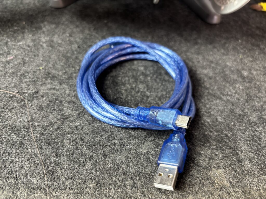
The Arduino Nano features a USB 2.0 Mini-B connector. This port not only delivers a regulated 5V to power the board but also enables serial communication with a computer. It allows you to program the microcontroller and receive data back from it.
The reset button restarts the currently running program on the Nano, similar to disconnecting and reconnecting the board. When pressed, the onboard “L” LED (wired to pin 13) typically flashes a few times, signaling that the bootloader is active before running the user code.
There are four built-in LEDs on the Nano:
LED_BUILTIN constant. It flashes during reset and bootloading.Note: TX and RX LEDs do not flash for activity on pins TX1 and RX0 directly.
The Nano is powered by the ATmega328P microcontroller. Here’s what it offers:
The 6-pin ICSP (In-Circuit Serial Programming) header is used to program the ATmega328P directly using an external programmer. Normally, code is uploaded via USB through the Arduino IDE. However, if the bootloader becomes corrupted or missing, you can reflash it using the ICSP header — even with another Arduino running the ArduinoISP sketch.

The bootloader is a small .hex file that runs when the board is powered. It checks whether a new program is being uploaded. If so, it loads the new program into memory. If not, it starts the program currently stored in Flash.
If you’re planning to get your hands on an Arduino Nano, here are some trusted options:
These are affiliate links. If you purchase through them, I may earn a small commission at no extra cost to you. Thanks for supporting the blog!
The Arduino Nano is a compact and practical microcontroller board, perfect for space-constrained projects or breadboard prototyping. Despite its small size, it offers a wide range of features and flexibility.
However, it does have limitations:
Still, it’s a great entry-level board that balances power, size, and price. Whether you’re a beginner or working on embedded projects, the Nano is a solid choice.