Ever wanted a night light that just knows when to turn on? In this project, we’ll build a simple automatic night light using an Arduino and an LDR (light-dependent resistor). When it gets dark, the LED turns on. When it’s bright, the light stays off — no switches, no fuss.

This project is perfect for beginners who want to explore how sensors work with Arduino. You’ll learn how to read analog input, set a light threshold, and control an LED based on real-world conditions.
Let’s get started and make your lights a little smarter.
Parts Required
- Arduino Uno Starter Kit: https://amzn.to/3GKRdQx
- Bread Board: https://amzn.to/3GDwQoz
- Jumper Wires : https://amzn.to/434rudw
- 5mm LEDs Assortment Pack : https://amzn.to/3Z4RAM4
- Photoresistor : https://amzn.to/4k1jpNo
- 10k-ohm resistor :https://amzn.to/3SnW3Wn
This post may contain affiliate links. If you purchase through these links, I may earn a small commission at no extra cost to you. It helps support this blog and keeps the projects coming—thanks for your support!
How It Works
This project uses a light sensor (LDR) to detect how bright or dark the environment is. The LDR is a special type of resistor that changes its resistance depending on how much light hits it:
- In bright conditions, the resistance drops low.
- In the dark, the resistance increases significantly.
We combine the LDR with a regular resistor to form a voltage divider. This setup sends a changing voltage signal to the Arduino’s analog input pin. When it’s bright, the voltage is higher; when it gets dark, the voltage drops.
The Arduino constantly reads this input value. If it detects that the room is dark (i.e., the value falls below a preset threshold), it sends a signal to turn on the LED. When the light comes back, the LED turns off again.
💡 Bonus tip: LDRs aren’t polarized — you can plug them in either direction, no problem.
This is the same principle used in automatic night-lights — simple, effective, and easy to build with just a few components.
Wiring the Circuit
Follow these steps to connect your components to the Arduino:
Let’s walk through how to wire the components for this light-activated night light:

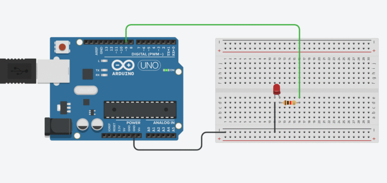
- Place the LDR on the breadboard, making sure each leg is on a separate row.
- Connect one leg to 5V on the Arduino.
- Connect the other leg to analog pin A0 — this is where we’ll measure the light level.
- Add a 10kΩ resistor to form a voltage divider:
- Connect one end of the resistor to GND on the Arduino.
- Connect the other end to the same row as the LDR leg going to A0.
This setup creates a voltage divider that adjusts the voltage at pin A0 based on the surrounding light. The darker it gets, the lower the voltage at A0 — and that’s how we know when to turn on the LED.
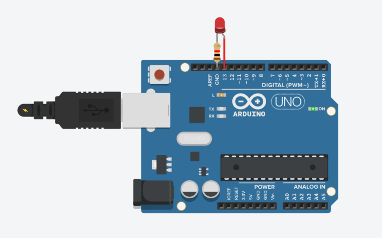
- Connect the LED:
- Insert the longer leg (anode) of the LED into digital pin 13.
- Insert the shorter leg (cathode) into GND.
- Note: Pin 13 on most Arduino boards already includes a current-limiting resistor, so you can safely connect the LED without an external resistor. (But you can always add a 220Ω if you want to be extra safe.)
- Upload the code using the Arduino IDE. Once running, the LED will automatically turn on when it gets dark.
Code Breakdown: What’s Happening Here?
const int ldrPin = A0;
const int ledPin = 13;
const int threshold = 500;  // light level threshold to turn on the LED

void setup() {
  pinMode(ledPin, OUTPUT);
  Serial.begin(9600);
}

void loop() {
  int lightLevel = analogRead(ldrPin);  // read value from 0–1023
  Serial.println(lightLevel);

  if (lightLevel < threshold) {
    digitalWrite(ledPin, HIGH);  // it's dark → turn on the LED
  } else {
    digitalWrite(ledPin, LOW);   // it's bright → turn off the LED
  }

  delay(200);
}
Link to Tinker CAD here
Let’s walk through what the sketch actually does under the hood:
- First, we connect the photoresistor to analog pin A0, which we use as an input to detect how much light is hitting the sensor.
- The LED is connected to digital pin 13, which acts as an output — the Arduino will send signals to this pin to turn the light on or off.
In the setup() function, we call <strong>Serial.begin(9600)</strong> to start serial communication. This allows the Arduino to send data to your computer, and if you open the Serial Monitor in the Arduino IDE, you’ll see real-time readings from the photoresistor.
Inside the loop()The Arduino runs continuously:
- Reads the analog value from A0 — this gives us a number between 0 and 1023, depending on how bright it is.
- That value is then divided by 4 (because analogWrite for PWM pins only accepts values between 0 and 255) — this scales the light level down to something the LED can use.
- The LED receives this value as a PWM signal (a type of “fake analog”), which makes it appear dimmer or brighter depending on the surrounding light.
⚡ In short:
More light → lower LED brightness
Less light → LED gets brighter automatically
This setup creates a smooth, real-time response that mimics how night-lights work — fading in as the room darkens, and fading out when it’s bright again.
Recommended Kits for Beginners:
- Elegoo Uno Super Starter Kit – perfect for learning and building
- Solderless Prototyping Breadboard Kit
- LED Project Pack