If you’ve already built a basic servo project and you’re ready for the next step, this one’s for you. In this project, we’re going to control two servo motors using two potentiometers, and on top of that, we’ll display their real-time angles on an I2C LCD screen. It’s an excellent exercise to get comfortable with reading multiple analog inputs, writing to servos, and outputting data to an LCD — all in one neat little system.
In this project, You’re going to learn how to read analog signals from two separate potentiometers and use those values to control the angles of two different servo motors. You’ll also learn how to wire and program an I2C LCD so you can display the raw input values and the calculated angles in real time.
This project brings everything together: input, processing, and output — both mechanical and visual. It’s simple to build, but very useful for real-world prototyping.
How It Works
At the heart of the project are the two potentiometers. Each pot outputs an analog voltage between 0 and 5V depending on how far it’s turned. The Arduino reads these voltages using analogRead(), which gives you a number between 0 and 1023. These values don’t directly mean anything to the servo, so we use map() to convert them into angles between 0 and 180 degrees.
Once we have those angles, we send them to the respective servo motors using servo.write(). So as you turn each knob, its corresponding servo moves in sync. The result is smooth, responsive manual control.

To make things more user-friendly and professional, we also hook up an I2C LCD display. This screen shows you the current analog value from each potentiometer and the calculated angle sent to the servo. That way, you can actually see what’s happening — no guessing, no blind testing.
This setup is super intuitive. It turns your Arduino into a real-time controller with visual feedback, making it great for applications like controlling robotic joints, pan-tilt camera rigs, or even servo-based animatronics.
Wiring Guide
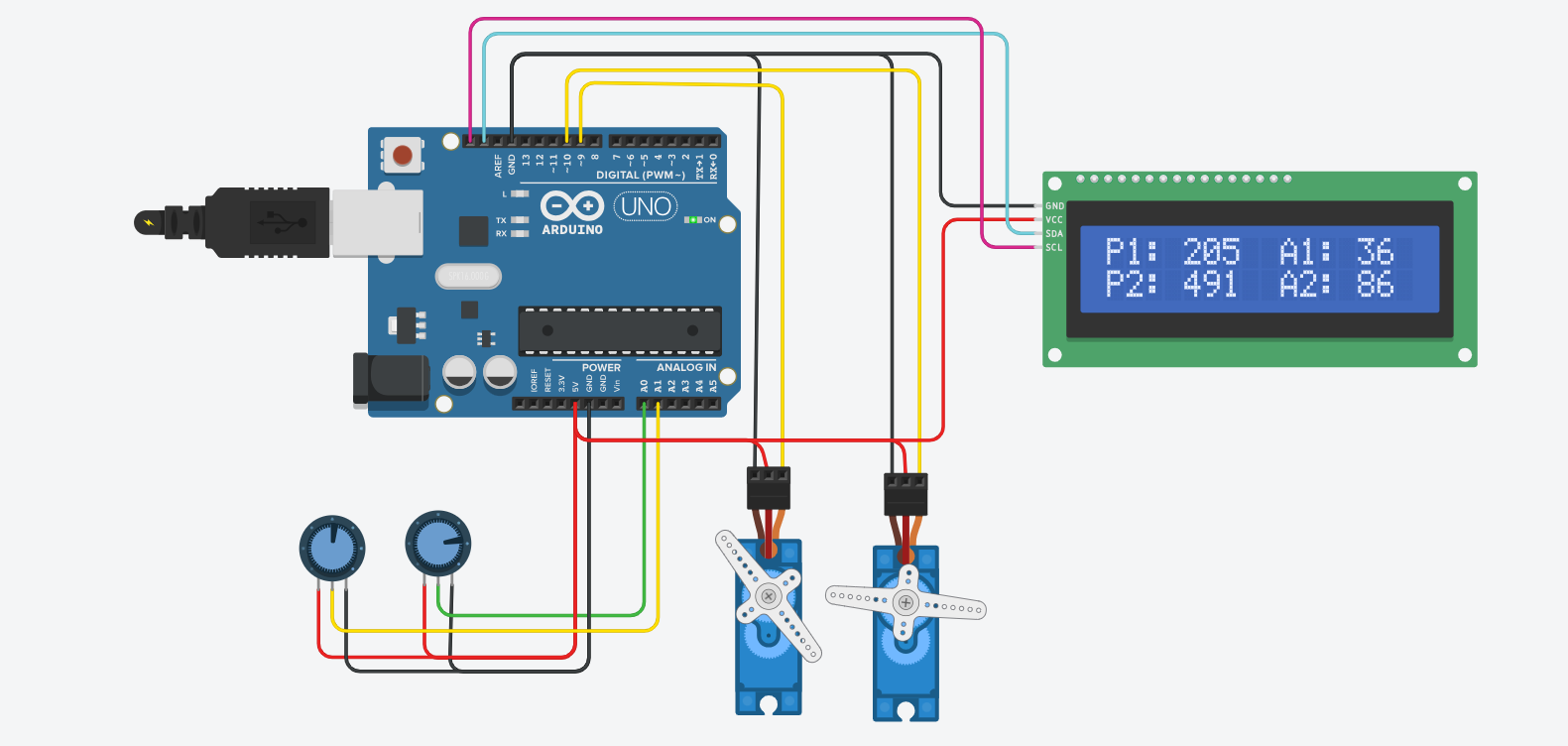
Let’s quickly walk through how everything should be connected. This is the backbone of the project — if your wiring isn’t solid, nothing will work right.
You’ll have two potentiometers. Each one has three pins: one side connects to 5V, the other side to GND, and the middle pin (the wiper) goes to an analog input on the Arduino — in this case, A0 and A1. These are your manual inputs.
Next, you have two servo motors. Each servo has three wires: brown/black for GND, red for 5V, and orange/yellow for the signal. Connect the signal wires of the servos to digital pins 9 and 10, respectively. If you’re using the Arduino’s 5V pin to power the servos, it may work for small ones like SG90 — but for smoother performance, especially with two or more servos, it’s recommended to use a separate regulated 5V power supply. Just remember to connect all GNDs together (Arduino, servos, and LCD).
Finally, the I2C LCD. It only needs two data lines: SDA and SCL. On an Arduino Uno, SDA is A4 and SCL is A5. You also connect VCC to 5V and GND to GND.
Once everything is wired up properly, you’ll have a nice feedback loop between your hands, the motors, and the screen.
The Code
Here’s the complete code for this project:
#include <Servo.h>      // Library for controlling servo motors
#include <Wire.h>        // Library for I2C communication
#include <LiquidCrystal_I2C.h> // Library for LCD I2C

Servo servo1;
Servo servo2;

int potPin1 = A0;
int potPin2 = A1;

int potValue1 = 0;
int potValue2 = 0;
int angle1 = 0;
int angle2 = 0;

LiquidCrystal_I2C lcd(0x27, 16, 2);

void setup() {
  servo1.attach(9);
  servo2.attach(10);

  lcd.init();
  lcd.backlight();
  lcd.begin(16, 2);
  lcd.print("Servo Control");
  delay(2000);
  lcd.clear();
}

void loop() {
  potValue1 = analogRead(potPin1);
  potValue2 = analogRead(potPin2);

  angle1 = map(potValue1, 0, 1023, 0, 180);
  angle2 = map(potValue2, 0, 1023, 0, 180);

  servo1.write(angle1);
  servo2.write(angle2);

  lcd.clear();
  lcd.setCursor(0, 0);
  lcd.print("P1:");
  lcd.print(potValue1);
  lcd.print(" A1:");
  lcd.print(angle1);

  lcd.setCursor(0, 1);
  lcd.print("P2:");
  lcd.print(potValue2);
  lcd.print(" A2:");
  lcd.print(angle2);

  delay(500);
}
The code begins with importing three libraries — Servo.h to control the servos, Wire.h for I2C communication, and LiquidCrystal_I2C.h for the LCD. Then we create two servo objects and define the pins connected to each potentiometer.
In the setup() function, we attach each servo to its respective PWM pin and initialize the LCD display. The LCD shows a welcome message for two seconds before clearing the screen for real-time updates.
Inside the loop(), we read the values from the potentiometers, convert them to angles using map(), and send those angles to the corresponding servos. Then we update the LCD to show both the raw analog values and the final servo angles.
The short delay at the end helps prevent the LCD from flickering too fast and gives the servos a moment to settle into their new positions.
❓ Frequently Asked Questions (FAQ)
Q: Can I use different types of servo motors?
Yes, most hobby servo motors like SG90 or MG90S will work perfectly. Just make sure the power supply is sufficient.
Q: What if nothing shows up on the LCD?
Try changing the I2C address in the code from 0x27 to 0x3F. If you’re not sure, use an I2C scanner sketch to find the correct address.
Q: The servo motors are shaking or not moving correctly — why?
This is usually caused by insufficient power. Consider powering the servos with a separate 5V regulated supply and always connect all grounds together.
Q: Can I extend this to three or more servos?
Absolutely. Just add more potentiometers and servos, and update the code accordingly. For many servos, you might also need a PCA9685 driver.
Q: Can I use this for real robotic joints?
Yes — this is a great prototype for manual control or calibration of robotic systems.
🛒 Recommended Components (Affiliate Links)
If you want to build this exact project, here are some parts I’ve personally used and recommend:
10kΩ Potentiometer (Knob included)
If you order through these affiliate links, I may earn a small commission — at no extra cost to you. It’s a simple way to support the blog and help me continue making detailed, beginner-friendly tutorials.
Project Extensions
With just a little more code, you can easily expand this into a full-fledged robotic controller. Add buttons to save angles, record motions, or switch modes. Replace one of the potentiometers with a joystick to gain two-axis control. Or use this setup as a manual calibration tool for any robotic arm.
This is one of those projects that starts simple, but has almost unlimited upgrade potential. Once you’re comfortable here, you’re already halfway to building your first custom robot arm.
Let me know if you want a version that saves movements to EEPROM or adds a third servo!