Have you ever wanted to move something smoothly with your hand and see it come to life using a servo motor? Whether you’re building a robotic arm, a remote-controlled car, or just exploring electronics, learning how to control a servo with a potentiometer is a solid step forward. It’s like giving your Arduino a wrist and a muscle
Let’s dive into it.
What is a Potentiometer?
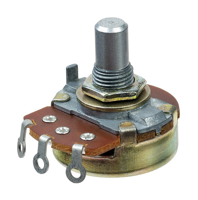
A potentiometer, often referred to as a “pot,” is one of the most common components in electronics when you need to control something gradually — like the brightness of an LED or the position of a motor. Internally, it acts as a variable resistor, offering a smooth range of values as you turn its knob. It has three pins: two are connected to a fixed voltage (5V and GND), and the third one, called the wiper, provides a changing voltage depending on the position of the knob. When wired into an Arduino, that wiper voltage can be read using the <mark style="background-color:#00d084;color:#000000" class="has-inline-color">analogRead()</mark> function, giving us a value between 0 and 1023. This is perfect for control scenarios where gradual input is needed.
It’s basically the same technology used in volume knobs, dimmer switches, or analog joysticks. And when paired with a servo motor, it allows you to create interactive systems where the mechanical movement mirrors the user’s hand motion. Simple, but incredibly powerful.
By the end of this tutorial, you’ll understand what a potentiometer and a servo motor are, how to connect them properly to an Arduino, and how to write the code so that turning the potentiometer changes the angle of the servo motor in real time.
What You Need
To complete this project, you’ll need an Arduino Uno (or any compatible board), a basic servo motor like the SG90, and a 10kΩ potentiometer. You’ll also need a handful of jumper wires and a breadboard for easy connections. If your servo draws a lot of current, consider using an external 5V power supply for stability.
Wiring Diagram
The connections are straightforward. The servo has three wires: the red one goes to 5V, the brown or black one goes to GND, and the yellow or orange one goes to a PWM pin on the Arduino, usually pin 9.
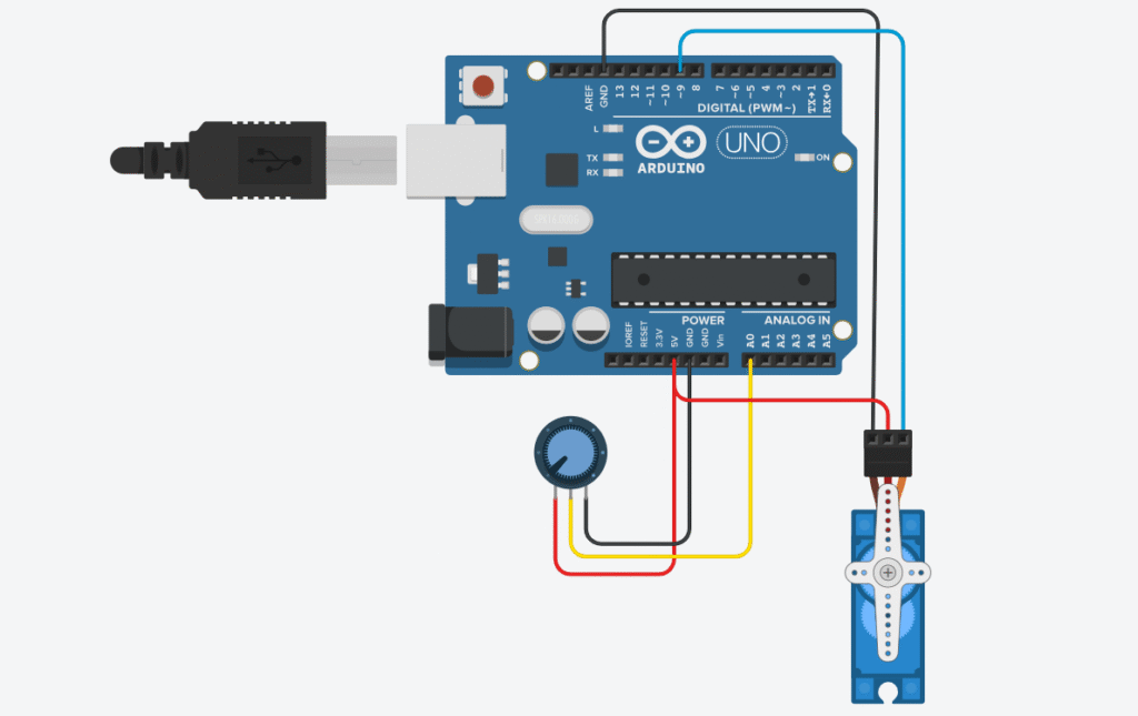
The potentiometer also has three pins: one to 5V, one to GND, and the middle one to the analog pin A0 on your Arduino. Once everything’s connected, you’ve basically set up a mechanical feedback loop.
⚠️ Note: If you’re using a powerful servo, don’t power it directly from the Arduino 5V pin. Use an external 5V source and connect all grounds together.
Arduino Code
#include <Servo.h>

Servo myServo;
int potPin = A0;       // Potentiometer connected to A0
int potValue = 0;      // Variable to store analog reading
int servoAngle = 0;    // Servo angle (0–180 degrees)

void setup() {
  myServo.attach(9);   // Connect servo to pin 9
}

void loop() {
  potValue = analogRead(potPin);               // Read potentiometer
  servoAngle = map(potValue, 0, 1023, 0, 180); // Convert to angle
  myServo.write(servoAngle);                  // Move servo
  delay(15);                                  // Smooth motion
}
Each section of the code has a clear job, so let’s walk through it step-by-step like we’re sitting side by side at your workbench.
We start with #include <Servo.h>, which pulls in the built-in Arduino Servo library. This library takes care of generating the PWM signals a servo needs to move, so you don’t have to manually time pulses — which is messy and complicated. With the library included, we can use simple commands like .attach() and .write().
Next, we declare Servo myServo;. This creates a servo object named myServo. Think of it as a remote control for the motor — from now on, anything we want the servo to do, we’ll tell it through this object.
Then in void setup(), we use myServo.attach(9); to tell the Arduino which pin our servo is connected to. This pin needs to support PWM — digital pin 9 is a common and safe choice.
Inside the loop(), the action begins. We use analogRead(potPin) to read the voltage from the potentiometer. This gives us a number between 0 and 1023. But the servo wants a number between 0 and 180 degrees, so we use the map() function to scale the input to the correct range. This new value is stored in servoAngle, and we send it to the servo using myServo.write(servoAngle);.
Finally, the delay(15); line adds a short pause to each loop. This isn’t strictly required, but it helps make the servo’s movement smoother and less jittery by giving it just a bit of time to physically reach the new position before the next command comes in. It’s a small tweak that makes the experience feel much more polished.
How It Works
Let’s break down what’s really happening behind the scenes. When you rotate the knob on the potentiometer, you’re changing the voltage that’s being sent into pin A0 on the Arduino. This voltage doesn’t come in as a direct voltage value, though — the Arduino reads it as an analog value between 0 and 1023, thanks to its built-in 10-bit analog-to-digital converter.
Now here’s the clever bit: servo motors don’t care about raw voltage or analog values — they want to know what angle to rotate to. So we use a simple function called map() to convert the potentiometer’s reading into a number between 0 and 180. This number is then passed to the servo motor using myServo.write(), and the motor instantly moves to that exact angle.
The result is an incredibly smooth and responsive control system. You’re essentially using your hand to manually “dial in” a position for the servo, with no lag, no sensors, and no complex programming. It feels natural, almost like your hand is directly controlling the mechanical part. This makes it not only a fantastic beginner project but also a valuable tool when prototyping robots or testing mechanical motion.
If your servo is twitchy or not responding, the first thing to check is the power. Some servos require more current than the Arduino can provide. Also, double-check that the middle pin of the potentiometer is really going to A0 — that’s a common mistake. If you need to dig deeper, use Serial.print() to display the analog values in the Serial Monitor so you can see if the pot is working correctly.
Controlling a servo with a potentiometer may seem basic, but it’s the foundation of many interactive systems. For instance, you can manually position robot arms, create camera gimbals, or even build light-tracking solar panels. It also teaches you a fundamental principle in electronics: how input translates into controlled output.
One of the most useful extensions of this project is creating a teach-and-repeat system, where you record potentiometer movements and have the servo repeat them later. This is the basis for a lot of industrial automation.
Frequently Asked Questions (FAQ)
Q: Can I use any servo motor for this project?
A: Most hobby servo motors like the SG90 or MG90S will work just fine. Just make sure they’re rated for 5V and don’t draw too much current if you’re powering them directly from the Arduino.
Q: What if my servo is jittering or not responding?
A: That’s usually a power issue. Try using a separate 5V power supply for the servo and make sure all grounds are connected.
Q: Can I control more than one servo?
A: Absolutely. You’ll just need more potentiometers and more pins. The Servo library can control up to 12 servos on most Arduino boards.
Q: Can I replace the potentiometer with a sensor?
A: Yes! You can use light sensors, joysticks, even ultrasonic sensors — as long as they output a readable analog or digital signal.
Q: Can I run this off battery power?
A: Sure, just make sure your batteries provide stable 5V (or use a voltage regulator), and that they can supply enough current for the servo.
Recommended Components (Affiliate Links)
Want to build this exact project? Here are some trusted parts I personally recommend:
- Arduino Uno R3 Starter Kit on Amazon
- SG90 Micro Servo Motor 9g
- 10kΩ Potentiometers (5-pack)
- Solderless Breadboard + Jumper Wires
- 5V 2A Power Supply for Servo Motors
If you purchase through these affiliate links, I may earn a small commission — at no extra cost to you. It’s a great way to support the blog and help me keep creating helpful content for makers like you. — and helps me keep creating beginner-friendly tutorials like this. Thanks for your support t 🙌
Final Thoughts
Controlling a servo with a potentiometer is one of those classic Arduino projects — simple, satisfying, and incredibly useful. It connects the physical world with code in a very tactile way.
Go try it out. Turn the knob. Watch your project move.
That’s the magic of DIY electronics.