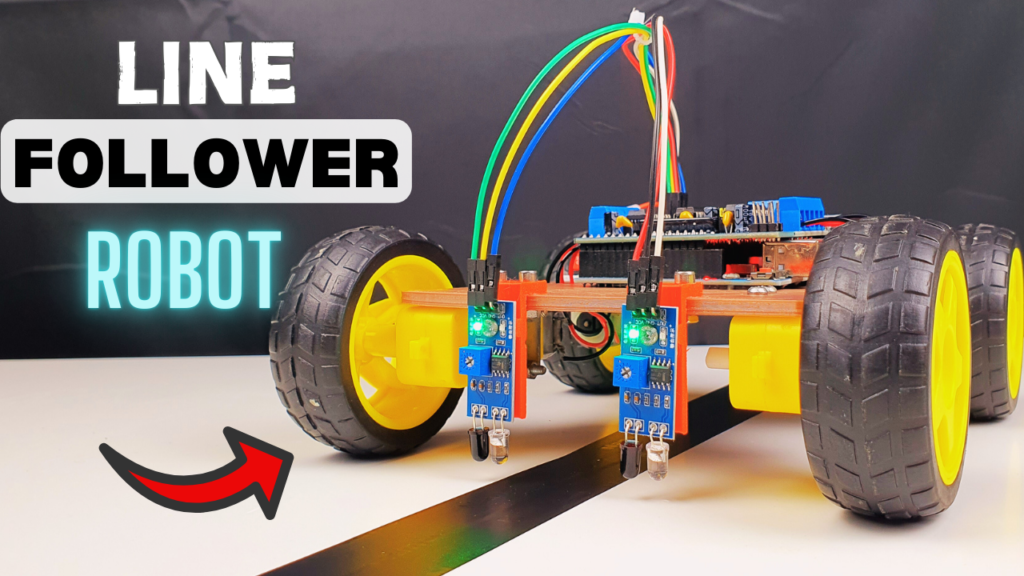
How to Make a Line Following Robot Using Arduino and L293D (Beginner-Friendly Guide)
Have you ever dreamed of building a robot that moves by itself, follows a path like it’s alive, and actually understands the world around it — well, sort of?
Then you’re gonna love this.
In today’s project, we’re building a Line Following Robot using Arduino, IR sensors, and the L293D motor driver. Whether you’re a student, hobbyist, or just plain curious, this is a classic project that teaches you the basics of automation, sensor logic, and motor control – all in one go.
But wait—what exactly is a line following robot?
Imagine laying a strip of black tape on the floor, and your robot follows it like a train on invisible tracks. It doesn’t need GPS. It doesn’t need Wi-Fi. It just uses a pair of smart little eyes (aka IR sensors) to “see” the line and stick to it like glue.
Sounds simple? It is. But it’s also the foundation of many real-world applications:
- Warehouse robots
- Factory AGVs (Automated Guided Vehicles)
- Mini delivery bots in offices
- And of course… those cute robots at tech fairs
By building this robot, you’re not just making a toy — you’re learning how real-world robots make decisions based on what they sense. That’s what makes it so cool.
Let’s break it down from the start.
Actually, I made a video about this project! So if you run into any issues along the way, watching that video is probably the easiest way to figure things out.
Parts You’ll Need:
Here’s the gear you’ll need to bring this little robot to life:
- Arduino Uno (or compatible board): https://amzn.to/4ixHpGT
- IR Sensors: https://amzn.to/4mjNoCr
- L293D Motor Driver Module: https://amzn.to/4lPHFE4
- HC-05 Bluetooth Module: https://amzn.to/3GDqDbS
- 4WD Robot Car Chassis: https://amzn.to/42rPtEf
- Li-ion battery pack (7.4V–12V) : https://amzn.to/3GntTZ4
- Battery holder: https://amzn.to/3EII9eg
- Jumper wires (male-male and male-female): https://amzn.to/3EvCFUh
- Screwdriver, nuts, bolts: https://amzn.to/44GfFwh
- Double-sided tape or zip ties: https://amzn.to/44CeMF6
This post may contain affiliate links. If you purchase through these links, I may earn a small commission at no extra cost to you. It helps support this blog and keeps the projects coming—thanks for your support!
Now let’s see how we can make this project.
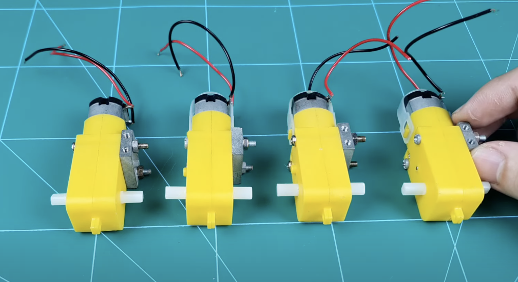
1. Preparing the motors
First, you’ll need to prepare 4 DC gear motors along with the mounting brackets — these usually come with the robot chassis kit, but if not, you can grab them separately online or at any DIY electronics store.
These motors are the heart of your robot’s movement, so make sure they’re the same type and gear ratio to avoid weird turns or uneven speed.
Next, attach the motors to the brackets using eight M3x45 screws and nuts. Tighten them firmly but not overly tight — you don’t want to crack the plastic mounts or strip the threads.
When it comes to wiring, don’t stress too much about the polarity just yet. Simply solder two wires to each motor’s terminals. You can easily reverse the rotation later by switching the wires when connecting to the motor driver. That’s the beauty of DC motors: plug-and-play… with a bit of trial and error
2. Printing the Base
After soldering the motors, you will need a chassis to make this project. I’ve designed a chassis in Autodesk Fusion 360, and if you have a 3D printer, don’t hesitate to download and print it.
👉 Download STL file on Cults3D
Now if you don’t have a 3D printer — that’s totally fine!
You can simply grab a small, flat piece of wood, acrylic, or even thick cardboard to act as your robot base. As long as it’s sturdy enough to hold the motors and electronics, it’ll do the job.
At this point, you should already have your chassis layout in mind.
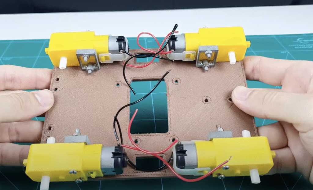
Let’s move on to mounting the 4 DC gear motors.
If you’ve got a hot glue gun — perfect. Just apply a generous amount of glue and press each motor firmly onto the base. Hold it for a few seconds to let it set.
Hot glue works surprisingly well for this kind of low-speed robot.
If you don’t have hot glue, double-sided tape is your backup plan. It might not be as strong, but hey, it works… kind of. Just don’t blame me when one of your motors suddenly flies off mid-turn like Fast & Furious.
For my setup, I used eight M3x10 screws to securely mount the motors onto the motor brackets.
Each motor is held firmly in place by attaching it to the bracket using one screw per corner — this keeps everything stable when the robot is moving.
Make sure the motor shafts are facing outwards and aligned properly, so the wheels can spin freely later without rubbing against the frame.
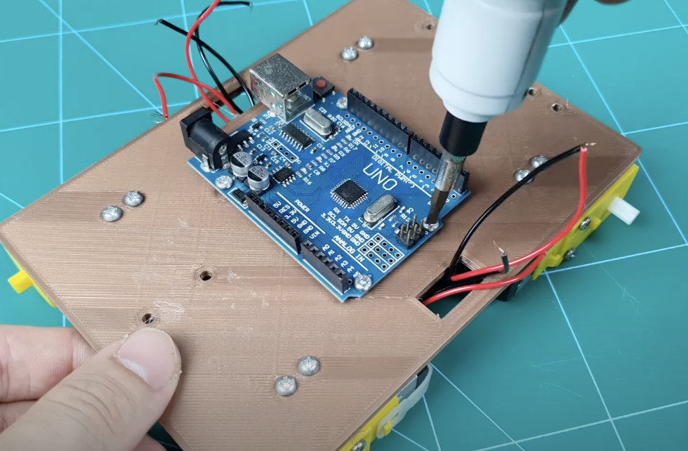
3. Attach the Arduino to the Base
Next, I mounted the Arduino Uno R3 onto the robot base using four M3 screw and nuts.
This setup not only keeps the board stable but also makes it easy to remove or replace later without risking damage to the pins or PCB.
Now, to be honest, you can mount the board however you like — even with duct tape if you’re feeling wild.
The easiest method? Just slap on some double-sided tape. It works… but I’m warning you, once you peel it off, it’s gonna leave behind a sticky mess that looks like a crime scene.
I skipped the part where we attach the four wheels to the motors.
Honestly, if you can’t figure out how to push-fit a wheel onto a motor shaft… maybe it’s time to go back to playing LEGO.
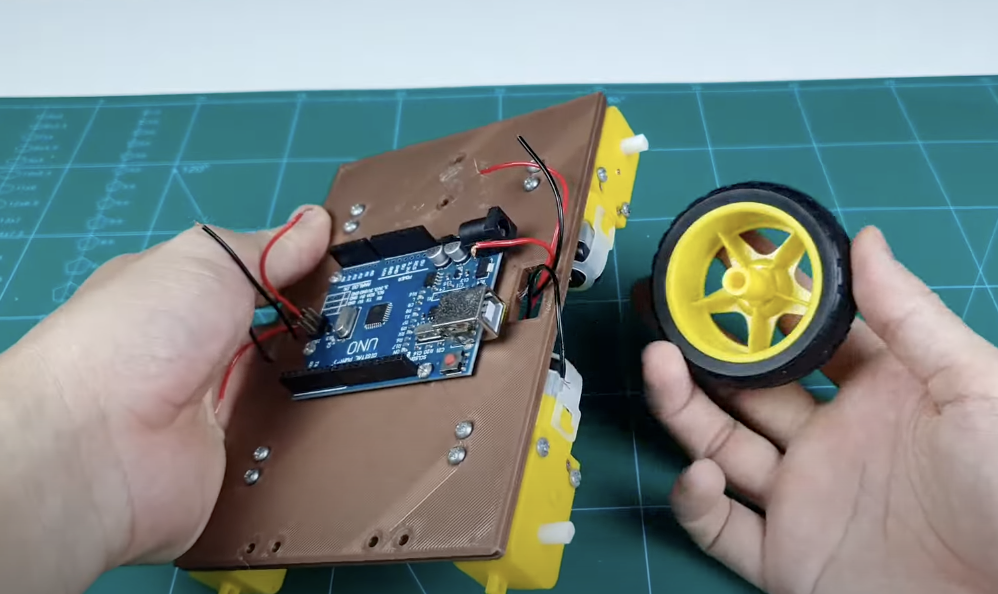
Just make sure the wheels spin freely and are firmly attached — you don’t want them flying off when the robot takes its first turn.
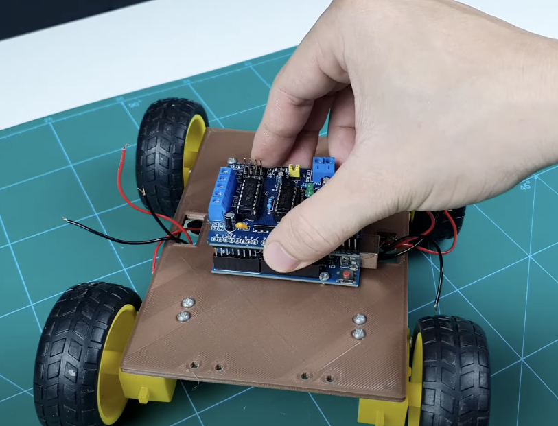
Once the Arduino is secured, it’s time to connect the motor driver.
I’m using an L293D motor driver shield, and the good news is: this part is stupidly simple.
Just plug it directly onto the Uno’s headers — like stacking LEGO. No wires, no fuss, done in 5 seconds.
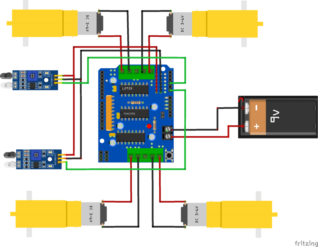
4. Wiring Motors to the L293D Motor Driver
Alright, now we’re getting to the important part — wiring up the L293D motor driver.
This module has 4 motor output pins, usually labeled as M1, M2, M3, and M4 (sometimes OUT1–OUT4 depending on the module).
Here’s how you should connect the motors:
- Connect the two left-side motors to M1 and M2
- Connect the two right-side motors to M3 and M4

Does the order matter?
Not really. If you wire it one way and your robot drives in reverse like it’s trying to run away from you — just swap the wires for that motor. That’ll instantly reverse the direction.
👉 Pro tip: Test your motor rotation before finalizing the setup. Saves you a headache later when you realize the robot’s doing donuts on the floor instead of going forward.
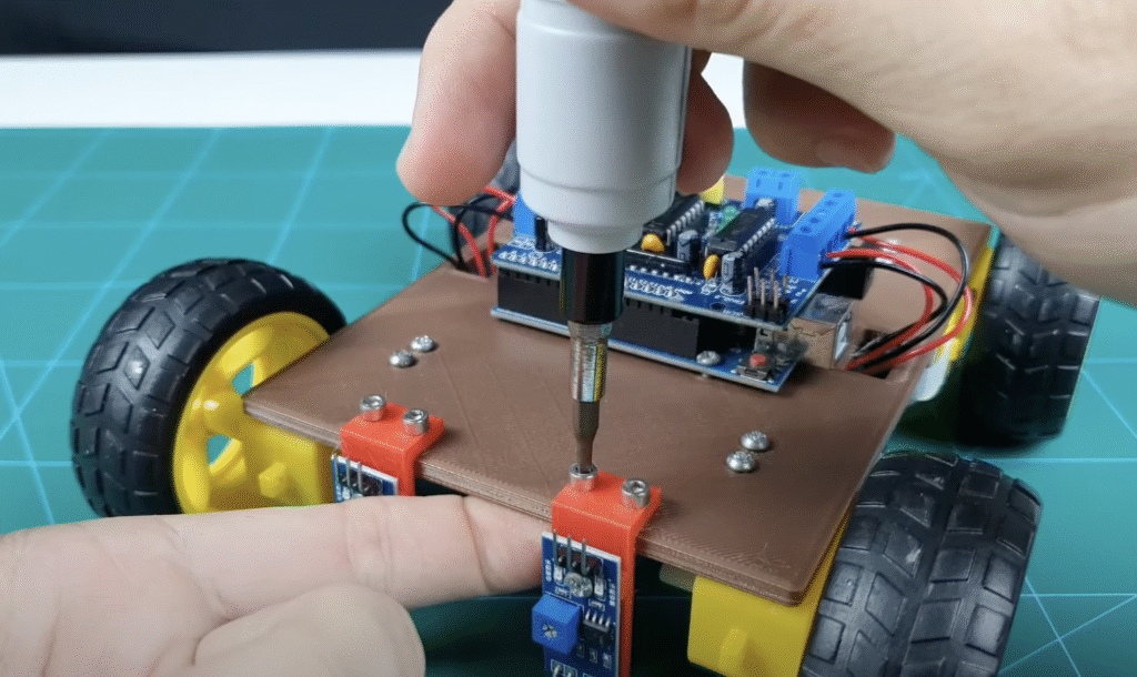
5. Attach the IR Sensors to the Base
Next up, it’s time to mount the two IR sensors onto the robot base. These are the “eyes” of your line-following robot, so you’ll want to place them right up front, facing downward, about 1–2 cm above the ground for best performance.
Here’s how I did it:
- I used two M3x10 screws to attach each sensor to a small L-shaped bracket.
- Then I fixed the bracket directly onto the robot base using screws or hot glue.
If you’re in a rush (or just lazy like me sometimes), you can skip the screws and just hot glue the IR sensors directly onto the base.
It works fine — just make sure they’re angled straight down and positioned evenly.
Remember: one sensor goes on the left, one on the right, and leave a small gap between them — ideally centered over where your black line will run.
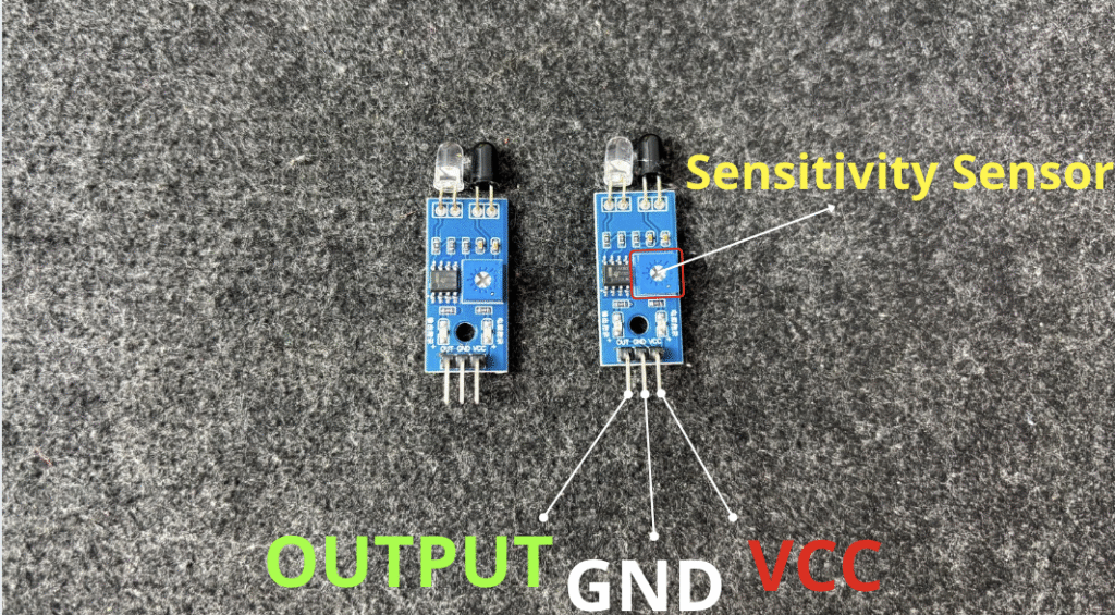
IR sensor modules typically have:
- VCC: Power supply (usually 5V)
- GND: Ground
- OUT: Output (HIGH or LOW depending on whether the sensor detects the line)
The OUT of the sensor on the left will be connected to the A0 and the other one will be connected to the A1.
GND and VCC will be fixed to the 0V and 5V of Arduino, respectively.
That’s all for the setup.
//Line Follower Robot
 //first , you need to insstall the motor driver for L293D motor driver
// Go to Sketch-> Include Librabry-> Manage Library-> Search for Adafruit Motor Shield V1
#include <AFMotor.h>

#define left A0
#define right A1

AF_DCMotor motor1(1, MOTOR12_1KHZ);
AF_DCMotor motor2(2, MOTOR12_1KHZ);
AF_DCMotor motor3(3, MOTOR34_1KHZ);
AF_DCMotor motor4(4, MOTOR34_1KHZ);

void setup() {

  pinMode(left,INPUT);
  pinMode(right,INPUT);
  Serial.begin(9600);

}

void loop(){

  Serial.println(digitalRead(left));

  Serial.println(digitalRead(right));


  if(digitalRead(left)==0 && digitalRead(right)==0){
    // Move forward
    motor1.run(FORWARD);
    motor1.setSpeed(150); // Run Speed from 0 to 255
    motor2.run(FORWARD);
    motor2.setSpeed(150);// Run Speed from 0 to 255
    motor3.run(FORWARD);
    motor3.setSpeed(150);// Run Speed from 0 to 255
    motor4.run(FORWARD);
    motor4.setSpeed(150);// Run Speed from 0 to 255
  }
  //Compare to sensors
  else if(digitalRead(left)==0 && !analogRead(right)==0){
    //turn right
    motor1.run(FORWARD);
    motor1.setSpeed(150);
    motor2.run(FORWARD);
    motor2.setSpeed(150);
    motor3.run(BACKWARD);
    motor3.setSpeed(150);
    motor4.run(BACKWARD);
    motor4.setSpeed(150);

  }
  //Compare to sensors
  else if(!digitalRead(left)==0 && digitalRead(right)==0){
    //Turn left
    motor1.run(BACKWARD);
    motor1.setSpeed(150);
    motor2.run(BACKWARD);
    motor2.setSpeed(150);
    motor3.run(FORWARD);
    motor3.setSpeed(150);
    motor4.run(FORWARD);
    motor4.setSpeed(150);

  }
  //No signals
  else if(!digitalRead(left)==0 && !digitalRead(right)==0){
    //Stop
    motor1.run(RELEASE);
    motor1.setSpeed(0);
    motor2.run(RELEASE);
    motor2.setSpeed(0);
    motor3.run(RELEASE);
    motor3.setSpeed(0);
    motor4.run(RELEASE);
    motor4.setSpeed(0);

  }

}
🔧 Recommended Arduino Starter Kits for Beginners
If you’re just getting started with Arduino, these beginner-friendly kits will help you learn faster and avoid the headache of missing parts. They all include essential components like LEDs, resistors, jumper wires, and an Arduino-compatible board.
- Arduino Official Starter Kit
Includes a genuine Arduino UNO board, project book, and components for 15+ tutorials.
👉 Check it on Amazon - Elegoo UNO R3 Super Starter Kit
Affordable and packed with sensors, LEDs, motors, and wires — great value.
👉 View the Elegoo Kit - Freenove Ultimate Starter Kit
Includes 200+ components, an Arduino-compatible board, and 50+ example projects.
👉 See the Freenove Kit
💡 Tip: Choose a kit with a good variety of components so you can build multiple projects without buying extra parts later.