Arduino Uno Pinout Explained (With Practical Tips for Beginners)
Introduction
If you’re just starting with Arduino, you’ll often hear about digital pins, analog pins, PWM, and more. But what do all these pins on the Arduino Uno actually do — and how do you use them in real projects?
In this post, we’ll walk through the pinout of the Arduino Uno, explain what each section is for, and give you practical tips so you can avoid confusion and start wiring like a pro.
💡 Whether you’re trying to blink an LED or build a robot, knowing the board’s pinout is the key to doing it right.
Section Breakdown
1. Digital I/O Pins (0–13)
- Used for reading or writing HIGH/LOW values
- Pins 0 and 1 also serve as Serial RX/TX
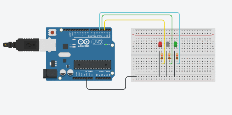
- Pins 3, 5, 6, 9, 10, 11 support PWM output
- Practical tip: Avoid using pins 0 and 1 if you’re uploading via USB — they can interfere with serial communication.
2. Analog Input Pins (A0–A5)
- Used for reading analog signals (e.g. sensors like potentiometers, temperature sensors)
- Can also be used as regular digital pins if needed
- Practical tip: A0–A5 are often used for sensors. Keep your wiring clean and label cables if using many.
3. Power Pins
| Pin | Function |
|---|---|
| 5V | Outputs 5V power (for sensors/modules) |
| 3.3V | Outputs 3.3V (lower power modules like ESP8266) |
| GND | Ground — you’ll use this a lot |
| Vin | Input voltage when powering with external adapter (7–12V) |
- Practical tip: Never power your Uno via 5V pin — always use Vin or the barrel jack for safety.
4. PWM Pins (marked with ~ symbol)
- Pins: 3, 5, 6, 9, 10, 11
- Used to simulate analog output (e.g. dimming LED, controlling motor speed)
- Practical tip: PWM is great for controlling things without using analogWrite() on every pin — but not all digital pins support it.
5. Serial Communication Pins
- Pins 0 (RX) and 1 (TX)
- Used for USB communication or Serial with other devices (like Bluetooth modules)
- Practical tip: If you’re using Serial Monitor in Arduino IDE, don’t connect anything to pins 0 and 1.
6. ICSP Header (for advanced users)
- Used to program the board directly or burn bootloaders
- Often not needed for beginners — but good to know it exists
📍 Infographic Suggestion
Tao có thể làm 1 ảnh Uno Pinout sơ đồ, chú thích theo từng nhóm chân (màu khác nhau), gắn vào bài luôn.
Ví dụ:
- 🔵 Digital I/O (0–13)
- 🟢 Analog (A0–A5)
- 🔴 Power
- 🟡 PWM (~)
- ⚫ Serial
- 🟣 ICSP
📦 Where to Use This Knowledge
Now that you know what each pin does, try building a simple circuit:
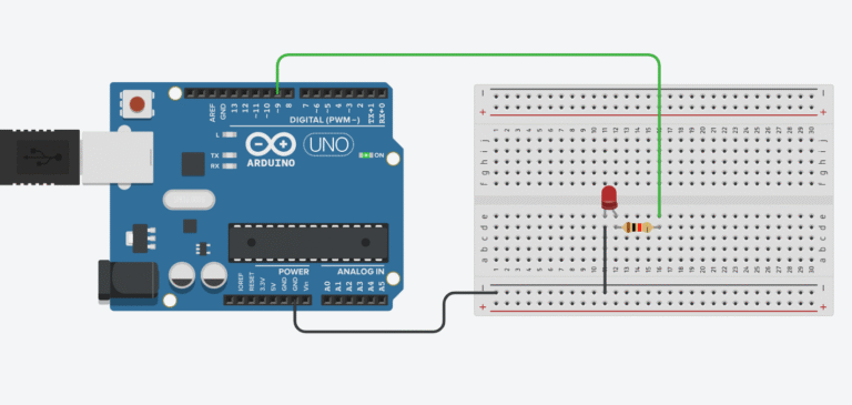
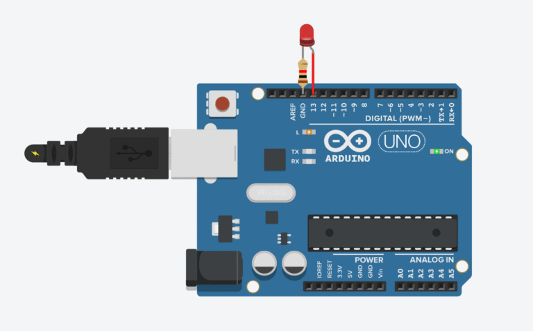
- Blink an LED using pin 13
- Read sensor data using A0
- Control a servo with pin 9 (PWM)
Once you know the layout, your wiring will be faster, cleaner, and more reliable.