Physical Address
304 North Cardinal St.
Dorchester Center, MA 02124
Physical Address
304 North Cardinal St.
Dorchester Center, MA 02124


Ever watched Knight Rider — that 80s show with the talking car KITT? If you have, you probably remember the sleek red lights on the front of the car that scanned left and right. In this project, we’re going to recreate that exact effect using Arduino and a few basic components. It’s a simple, beginner-friendly project that teaches you about LED sequencing, timing, and control logic.
Whether you’re just getting into Arduino or looking for a quick weekend build, this one’s both fun and satisfying to make. Plus, it looks really cool once it’s done!
This post may contain affiliate links. If you purchase through these links, I may earn a small commission at no extra cost to you. It helps support this blog and keeps the projects coming—thanks for your support!
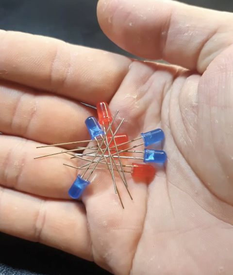
LEDs (light-emitting diodes) are tiny components that light up when a small current flows through them — but there’s a catch: they only work in one direction. That’s because LEDs are polarized, meaning they have a positive leg (called the anode) and a negative leg (the cathode). The longer leg is usually the positive one, and it needs to be connected to the positive side of your power source.
In our Knight Rider project, the Arduino sketch controls the blinking pattern of the LEDs, telling them when to turn on and off. But here’s something important — LEDs don’t need a lot of voltage to shine. In fact, the voltage from an Arduino pin is higher than what an LED actually needs. That’s why we use resistors. Resistors help limit the current so the LEDs don’t get overloaded and burn out.
Want to get creative? You can swap in different colors and place your LED strip anywhere — on a toy car, your bicycle, your desk, or even frame it around a speaker or picture. On an Arduino Uno, you can control up to 10 LEDs individually before you run out of digital pins.
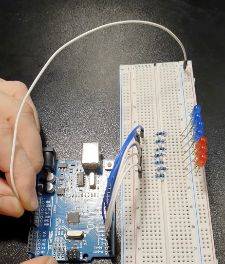
Insert the LEDs into the breadboard with their shorter, negative legs in the GND rail at the top of your breadboard. Then connect this rail to GND on the Arduino.
👉 Don’t have the parts yet?
Check out this Arduino LED Starter Kit — it includes everything you need for this project and more!
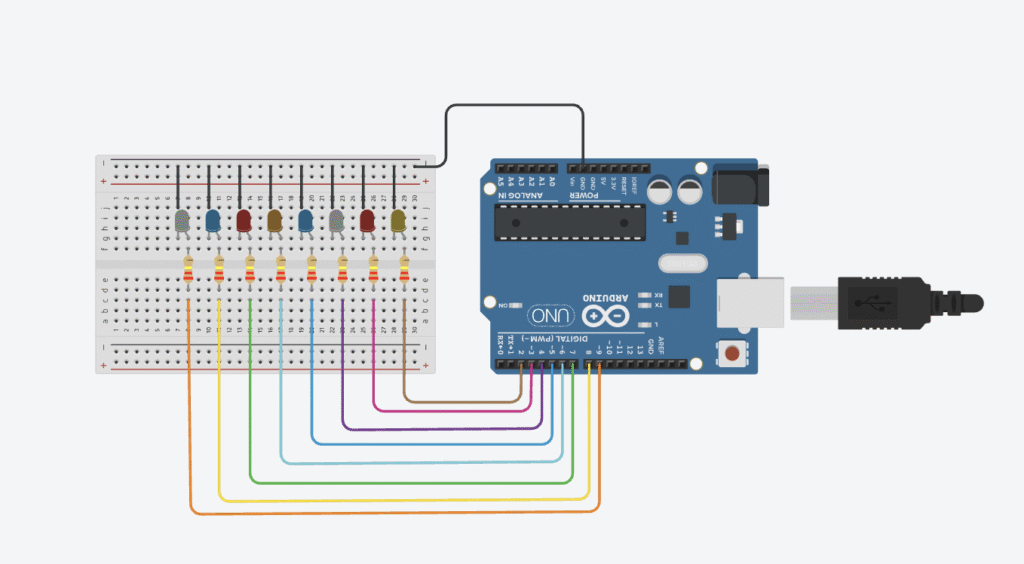
Connect the LEDs in sequence to Arduino digital pins 2–9, as shown in the following circuit diagram. Place a 220-ohm resistor between each LED and digital pin, ensuring that the resistors bridge the center divide in the breadboard.
| LEDS | Arduino |
| Positive Legs | Pins 2 to 9 using Resistor |
| Negative Legs | GND |
The sketch sets the pins connected to the LEDs as outputs, and then defines a function to turn all the LEDs off at the same time. This function is called in the loop cycle to turn the LEDs off, and then the LEDs are turned on one at a time—with a 200-millisecond delay between each one—to create a sweeping effect. Another loop sends the sequence back the other way.
Simulation on Tinker Cad here
// Knight Rider LED Chaser
// Inspired by the classic 80s TV series
// Rewritten and explained by Lee Curiosity

void setup() {
  // Set pins 2 to 9 as outputs for the LEDs
  for (int pin = 2; pin <= 9; pin++) {
    pinMode(pin, OUTPUT);
  }
}

// Turn off all LEDs before lighting the next one
void turnOffAllLEDs() {
  for (int pin = 2; pin <= 9; pin++) {
    digitalWrite(pin, LOW);
  }
}

void loop() {
  // Sweep LEDs from left to right
  for (int pin = 2; pin < 9; pin++) {
    turnOffAllLEDs();
    digitalWrite(pin, HIGH);
    delay(200); // LED stays on for 200 milliseconds
  }

  // Sweep LEDs back from right to left
  for (int pin = 9; pin > 2; pin--) {
    turnOffAllLEDs();
    digitalWrite(pin, HIGH);
    delay(200);
  }
}
If your code uploads successfully but the LEDs aren’t lighting up as expected, don’t panic — here are some common things to check: