Physical Address
304 North Cardinal St.
Dorchester Center, MA 02124
Physical Address
304 North Cardinal St.
Dorchester Center, MA 02124


So you just got your Arduino Uno and you’re staring at this blue board full of mysterious pins… What the heck is “A0–A5”? What’s “VIN”? And what happens if you stick a wire into “RESET”?
Don’t worry – in this guide, I’ll walk you through the Arduino Uno pinout step-by-step so you actually know what each pin does (and how not to fry your board on day one).
Before you start wiring up LEDs or sensors, you need to understand the pinout – short for “pin layout.”
This post may contain affiliate links. If you purchase through these links, I may earn a small commission at no extra cost to you. It helps support this blog and keeps the projects coming—thanks for your support!
Want to get started with the Uno? Here’s the Arduino Uno Kit I recommend – perfect for beginners and great for most basic projects.
The Arduino Uno pinout is basically a map that shows what each pin on the board can do. Just like how a keyboard has different keys for different functions (letters, numbers, etc.), the Arduino has digital pins, analog pins, power pins, and special-purpose pins – each with their own role.

There are three main methods to supply power to the Arduino Uno:
Barrel Jack – Also known as the DC power jack, this input is typically used with a wall adapter. It supports voltages ranging from 5V to 20V, but it’s best to stick within 7–12V. Voltages above 12V can cause the voltage regulators to overheat, while anything below 7V may lead to instability.
Looking for an official Arduino Uno board or power adapter?
Get the Arduino Uno R3 on Amazon
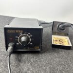
Power Supply Adjustable DC
VIN Pin – This pin allows the board to be powered by an external source. The input voltage should be within the recommended 7–12V range, similar to the barrel jack.

USB Cable – Connecting the Arduino to a computer via USB provides 5V at up to 500mA.

There’s a polarity protection diode between the barrel jack’s positive terminal and the VIN pin, rated at 1A, to prevent damage from reverse polarity.
The power source you choose determines how much current is available to your entire setup. For example, USB power limits you to around 500mA, which is shared between the MCU, built-in components, and anything connected externally. When using VIN or the barrel jack, current availability depends on the onboard 5V and 3.3V regulators.
Need to power multiple sensors? Use a breadboard power supply module for stable 3.3V and 5V rails.
5V and 3.3V – These pins output regulated voltages (5V and 3.3V) that you can use to power external modules or sensors as long as they’re within safe current limits.
GND – The board includes five GND pins, all of which are internally connected. They serve as the electrical return path and reference voltage. Always connect your external components to Arduino’s GND to ensure a common reference.
The Arduino Uno features six analog input pins (A0 to A5) that use an internal Analog-to-Digital Converter (ADC).
These analog pins are primarily used for reading continuous voltage signals, but they can also be configured as digital I/O if needed.
So, what is ADC Conversion?
ADC stands for Analog to Digital Converter. It’s a circuit that transforms analog voltage levels into digital signals. This process allows the microcontroller to measure and work with analog input.
Each analog pin on the Arduino Uno supports a 10-bit resolution, which means it maps input voltages (0–5V) to digital values ranging from 0 to 1023.
A real-world example is a temperature sensor like the LM35. It outputs a voltage that changes based on the temperature it’s reading. The Arduino’s ADC converts this voltage into a digital value so your code can understand and respond to temperature changes.
Want to try this? Here’s the LM35 Temperature Sensor
The Arduino Uno includes 14 digital I/O pins, numbered D0 through D13.
Pin 13 is connected to the onboard LED.
Pins 3, 5, 6, 9, 10, and 11 support PWM (Pulse Width Modulation).

Important notes:
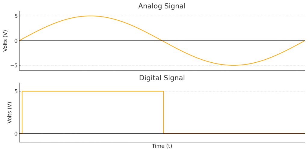
Digital signals represent voltage in binary: either 0 (LOW) or 1 (HIGH). Digital pins on the Arduino can be set as either inputs or outputs, depending on your project.
When configured as output, digital pins send out either 0V or 5V.
When configured as input, they receive voltage from external devices. The voltage is interpreted according to these thresholds:
If the voltage falls between 0.8V and 2V, the reading may be unreliable. Always ensure that your external components match the Arduino’s logic levels.
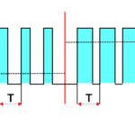
PWM is a method of encoding information or controlling power by rapidly switching a digital signal on and off. PWM signals have two properties:
Arduino’s PWM pins operate at a default frequency of ~500Hz. You can use PWM to control devices like DC motors, servos, and LEDs for dimming or speed regulation.
Serial (TTL) – Digital pins 0 (RX) and 1 (TX) are the Uno’s hardware serial pins and are used for communication via USB or with other serial devices.
What is Serial Communication?
Serial communication allows data transfer between the Arduino and other devices (like computers, GPS modules, or serial sensors). It takes place on digital pins 0 and 1 or via the USB port. Arduino also supports additional serial ports using the SoftwareSerial library.
Most microcontrollers include hardware modules for serial communication. However, software serial uses interrupt-based timing to emulate serial ports on any digital pin. It works but is slower and more CPU-intensive compared to hardware serial.
SPI stands for Serial Peripheral Interface. It’s a fast, full-duplex protocol used to talk to multiple devices over a shared bus. The Arduino Uno supports SPI on the following pins:
SPI is typically used for modules like SD cards, TFT screens, and shift registers
For SPI examples, check out:
👉 TFT SPI Display Module
👉 MicroSD Card Adapter for Arduino
One of my projects using SPI communication :
I2C (Inter-Integrated Circuit) is a two-wire protocol used to communicate between the Arduino and I2C-enabled devices.
Each I2C device has a unique address, and up to 255 devices can share the same bus. It’s commonly used for sensors, displays, and RTC modules.
👉 OLED I2C Display (0.96”)
👉 DS3231 I2C Real Time Clock Module
Aref – Reference voltage for analog input (used when you’re providing an external analog reference).
ICSP stands for In-Circuit Serial Programming. It’s a set of six pins that allow you to burn the bootloader or upload firmware to the Arduino using an external programmer. These pins connect directly to the microcontroller and are also shared with the SPI interface.