Physical Address
304 North Cardinal St.
Dorchester Center, MA 02124
Physical Address
304 North Cardinal St.
Dorchester Center, MA 02124

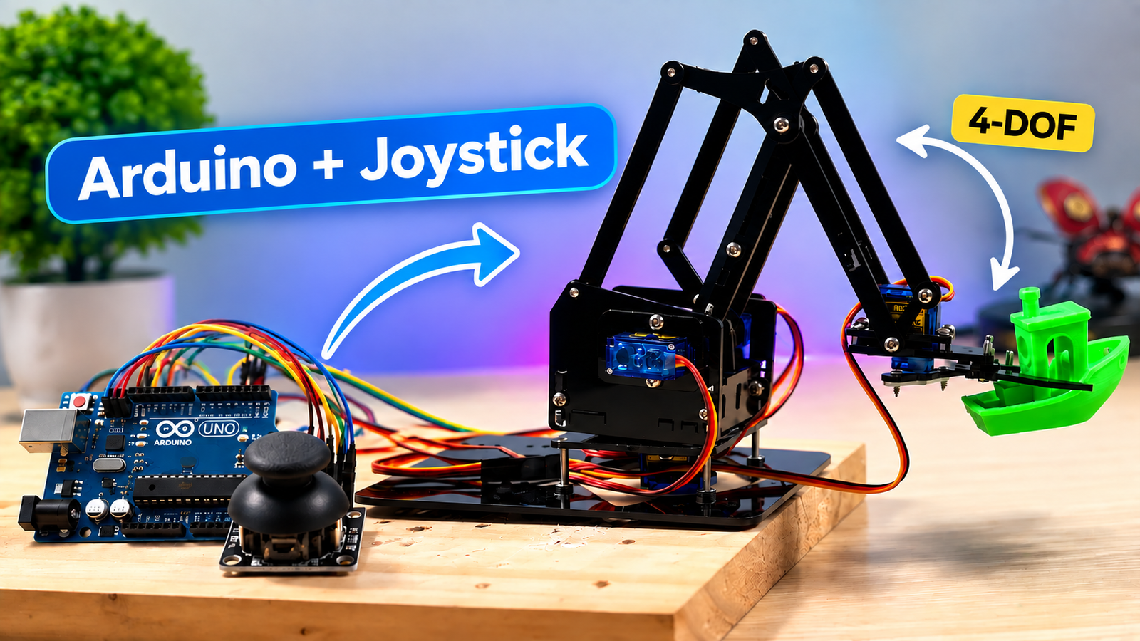
Have you ever wondered how a robotic arm knows which direction to move, how it controls each joint, or how it can repeat the same sequence of movements automatically?
In this project, we will explore a Mini 4-DOF Robot Arm controlled by Arduino. Instead of focusing only on assembling the robot, we will look at the basic concepts behind its operation, starting with degrees of freedom, potentiometers, and servo motors.
Then, we will learn how to control the robot arm using joysticks and explore a feature called Teach and Play, which allows us to record a sequence of movements and replay it automatically.
Let’s start with the basics.
Before controlling the robot arm, we need to understand an important concept: DOF.
DOF stands for Degrees of Freedom. In simple terms, it describes the number of independent movements a mechanism can perform.
Imagine an object floating freely in three-dimensional space. It can move along three directions: the X, Y, and Z axes. It can also rotate around these three axes.
These are six possible independent movements: three translational movements and three rotational movements.
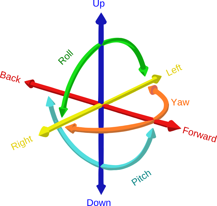
However, a robot arm does not always have six degrees of freedom. Its DOF depends on its mechanical structure and the movements its joints can perform.
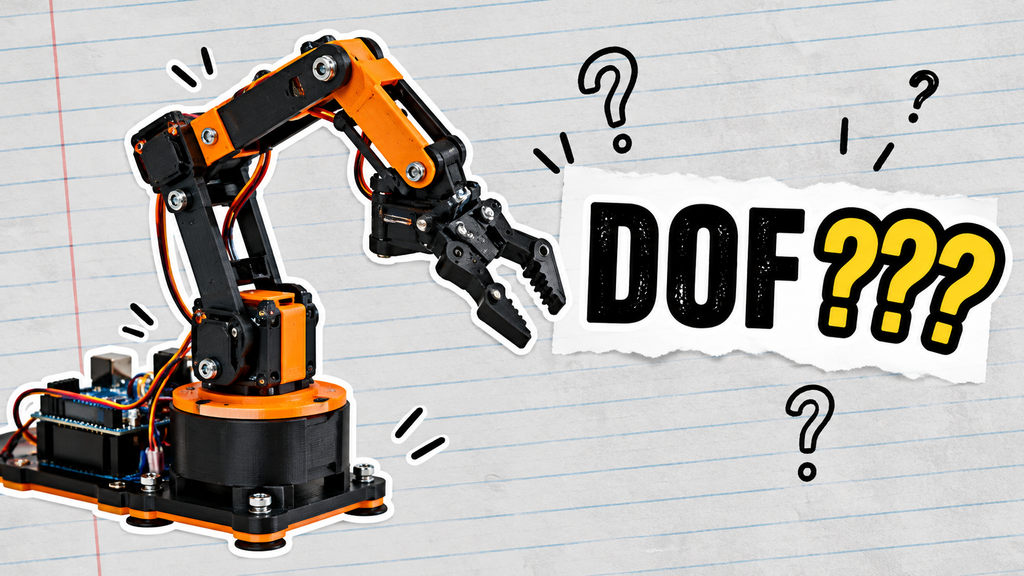
Our mini robot arm has four independently controlled movements, each operated by a servo motor.
The gripper counts as one degree of freedom because its opening and closing movement is independently controlled.
Therefore, this robot arm has four degrees of freedom, or 4 DOF.
Understanding DOF helps us understand how many independent movements we can control and what kinds of tasks the robot arm can perform.
Now that we understand the robot’s movement, let’s look at how we can control a servo motor.
A potentiometer is a variable resistor. Unlike a fixed resistor, its resistance can change when we rotate its shaft.
Inside a typical potentiometer, a movable contact slides along a resistive element. When we turn the knob, the contact changes position, which changes the electrical output voltage when the potentiometer is connected as a voltage divider.
This is why a potentiometer is useful as a physical control input.
For example, when you turn the knob clockwise, the output voltage may increase. When you turn it in the opposite direction, the voltage may decrease. The exact direction depends on how the potentiometer is wired.
Arduino cannot directly understand the physical position of a potentiometer knob. Instead, it reads the voltage from the potentiometer’s output pin.
For a typical 10-bit Arduino analog input, analogRead() returns a value from 0 to 1023.
These values represent the measured voltage, not the resistance itself.
When we rotate the potentiometer, Arduino receives a changing numerical value. We can then use this value to control another device, such as a servo motor.
A servo motor is useful for robotic arms because it can move to a commanded angular position.
In this example, the potentiometer acts as the input device, while the servo motor acts as the output device.
The basic control process is:
Potentiometer → Arduino → Servo motor
First, we connect the potentiometer’s output pin to Arduino’s analog input A0.
Arduino continuously reads the analog value. However, the potentiometer reading ranges from 0 to 1023, while our example servo control uses an angle range from 0 to 180 degrees.
These are two different ranges, so we need to convert one into the other.
Arduino provides a function called map() that can convert a value from one range into another.
Conceptually, the conversion looks like this:
The program then sends the calculated angle to the servo using servo.write(angle).
As we rotate the potentiometer, the calculated angle changes, and the servo moves toward the corresponding position.
This example introduces an important principle in control systems: a physical input is converted into a numerical value, processed by a controller, and used to generate a physical output.
The same principle will be used when we control our robot arm with joysticks.
Note: The 0–180° range is an illustrative example. The usable range of a real servo depends on its specifications and mechanical installation.
A joystick makes robot control more intuitive because we can move a stick instead of rotating a knob.
Most analog joysticks contain two potentiometers, one for the horizontal axis (X) and another for the vertical axis (Y). Moving the stick changes the output voltages of these potentiometers.
Arduino reads these voltages through its analog inputs and converts them into numerical values.
In our project, three analog signals are used to control three servo motors.
| Input | Robot arm movement |
|---|---|
| VRX1 — A0 | Base rotation |
| VRY1 — A1 | Shoulder joint |
| VRX2 — A2 | Elbow joint |
The gripper is controlled separately using the joystick’s push button connected to digital pin D2.
When the joystick moves horizontally or vertically, the corresponding analog reading changes. Arduino processes this reading and maps it to an angle within the configured servo limits.
For example, when we move the first joystick along its X-axis, the base servo changes its angle. Moving the joystick along its Y-axis controls the shoulder joint. The second joystick’s X-axis controls the elbow.
The important point is that each input is assigned to a specific movement. This allows us to control different joints independently.
Analog signals are not always perfectly stable. Even when a joystick is released, its readings may fluctuate slightly around its center value.
If Arduino reacts to every small fluctuation, the servo motors may move unintentionally or appear to vibrate.
To reduce this problem, our code uses a feature called a dead zone.
A dead zone is a small range around the joystick’s calibrated center. When the reading remains inside this range, the program ignores the input. When the reading moves outside the range, Arduino updates the corresponding servo position.
Our code uses a dead-zone threshold of 20 around the calibrated center values.
This helps prevent unwanted movements when the joystick is near its resting position.
In the current program, the base, shoulder, and elbow are limited to angles between 40° and 140°.
Why not simply allow the servos to move through their entire nominal range?
The mechanical structure may not safely support the full range of a servo. Moving too far could cause the arm to collide with another part, stretch wires, or place unnecessary stress on the joints.
By defining software limits, we can restrict the commanded movement to a more suitable range.
However, software limits alone do not guarantee mechanical safety. The actual limits should be tested on the assembled robot.
Now that we understand the hardware, let’s look at how the main parts of the program work together.
Our program uses two important Arduino libraries:
The program also separates the robot’s operation into several tasks.
When the Arduino starts, the program attaches each servo object to its assigned digital pin.
The four servos control the base, shoulder, elbow, and gripper. The program then commands their initial positions and attempts to load previously saved teaching data from EEPROM.
This initialization prepares the robot for manual control or playback.
During normal operation, Arduino reads the three analog joystick signals.
Each signal is checked against its calibrated center and dead zone. If the joystick moves outside the dead zone, the program maps the analog reading to the corresponding servo angle.
The servo is then commanded to move to the new position.
This process repeats continuously, allowing the robot arm to respond to joystick movements.
The push button connected to D2 changes the gripper between its configured closed and released positions.
The code detects a button press by comparing the current button state with the previous state. This allows the program to respond to a new press instead of repeatedly toggling the gripper while the button remains held down.
The button connected to D4 has a different purpose.
A single click saves the current positions of all four servo motors. A double-click starts playback if at least one position has been saved.
This creates two operating modes: manual control and automatic playback.
When playback is active, the program executes the playback routine rather than reading joystick inputs for normal manual control.
Teach and Play is a simple way to program a robot’s movements without manually writing every target angle into the code.
Instead of specifying all the servo angles in advance, we physically move the robot arm to the positions we want and save them.
Arduino then replays the recorded positions in the same order.
Let’s see how it works.
Use the joysticks to move the robot arm to the desired position.
You can adjust the base, shoulder, and elbow, then open or close the gripper using its button.
When the robot reaches the position you want, press the Save button once.
Arduino records the current angle of each servo as one complete position.
Move the robot arm to another position and press Save again.
For example, you could teach the following positions:
These are example teaching positions. The actual sequence depends on how you move the robot during teaching.
The current program supports up to 20 saved positions.
After saving the positions, double-click the same Save button.
Arduino starts playback and moves through the saved positions in sequence.
Instead of instantly jumping to the target angle, the program interpolates between the starting and target angles over a movement period of approximately one second. It updates the servo commands repeatedly during this period, creating a smoother transition between positions.
After reaching each target, the program pauses briefly before continuing to the next position.
When the robot reaches the last saved position, the playback index returns to the first position.
This means the robot continuously repeats the taught sequence until playback is stopped.
In the current code, pressing the Save button during playback stops the sequence and clears the saved teaching positions. The recorded data is also stored in EEPROM when positions are saved, allowing it to be loaded again after the Arduino restarts.
Important: The current implementation clears the teaching sequence when playback is stopped using this button. It is not a separate pause-and-resume function.
A pick-and-place task is a good way to demonstrate what the robot arm can do.
The goal is simple: move an object from one location to another.
First, use the joystick to move the robot arm toward the object. Save that position. Next, close the gripper and save the new position. Then move the arm toward the destination, save the position, and open the gripper to release the object.
Once the sequence has been taught, double-click the Save button to start playback.
The robot arm will move through the recorded positions automatically.
This demonstration combines several concepts we have covered:
Although this is a basic demonstration, it illustrates the foundation of movement sequencing in robotics.
The robot will not automatically detect objects or calculate an ideal trajectory. It simply repeats the positions you have taught it. Accurate and reliable operation therefore depends on careful teaching, stable mechanics, and suitable servo power.
This mini robot arm is more than a simple assembly project. It demonstrates how hardware, programming, and control logic work together.
By building and experimenting with it, you can learn:
Degrees of Freedom: How a robot’s independent joints determine its possible movements.
Analog Input Processing: How potentiometers and joysticks provide signals that Arduino can read and interpret.
Servo Motor Control: How numerical values can be converted into target angles for physical movement.
Input Filtering: How a dead zone helps reduce unwanted responses to small analog fluctuations.
Data Storage: How EEPROM can preserve a sequence of taught positions across restarts.
Movement Sequencing: How multiple servo positions can be recorded and replayed to automate a repetitive task.
These concepts provide a useful foundation for more advanced robotics projects, including robotic arms with inverse kinematics, sensor feedback, object detection, and more sophisticated motion planning.
In this tutorial, we explored how a Mini 4-DOF Robot Arm works, from understanding degrees of freedom to controlling servo motors with potentiometers and joysticks.
We also examined how Arduino reads analog signals, applies a dead zone, limits servo angles, and controls the gripper with a button.
Finally, we explored Teach and Play, which allows the robot arm to record up to 20 positions and repeat them automatically.
The most important concept is that a robot arm combines physical mechanisms, input signals, and programmed logic to perform controlled movements. Once you understand these basics, you can start developing more advanced robotic applications.
If you build this project, try teaching your robot a simple pick-and-place sequence and experiment with different positions.
Have questions about the Arduino code or robot arm control? Leave a comment below, and let’s discuss it!